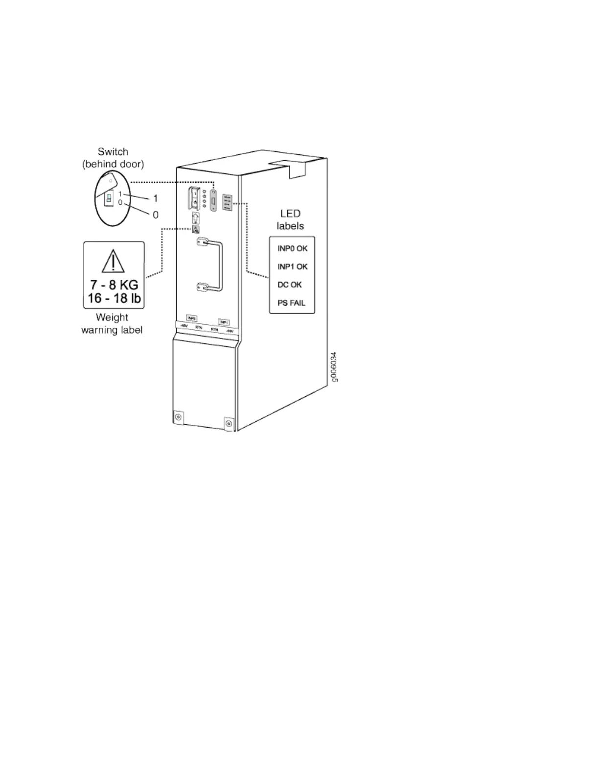
See Figure 20 on page 53.
Figure 20: DC Power Supply in an EX9214 Switch
Each power supply has two power inlets: one located at the top of the power supply and another that
requires a dedicated power feed, located directly above the power supply. If you plan to operate a
maximally congured DC-powered switch, we recommend that you use a dedicated customer site circuit
breaker rated for 208 A (104 A per supply) (–40 VDC) minimum, or one that complies with the by local
code.
If you plan to operate a DC-powered switch at less than the maximum conguraon, we recommend
that you provision a circuit breaker according to respecve Naonal Electrical Code and customer site
internal standards to maintain proper level of protecon for the current specied above or each DC
power supply rated for at least 125% of the connuous current that the system draws at –40 VDC.
DC Power Supply Conguraons
EX9214 switches support four DC power supplies, installed vercally at the rear of the chassis in slots
PEM0 through PEM3 (le to right), in two zones: power supplies in slots PEM0 and PEM2 provide
power to the lower fan tray, line card slots 6 through 11, and SF slots 1 and 2; power supplies in slots
PEM1 and PEM3 provide power to the upper fan tray, line card slots 0 through 5, and SF slot 0. There
must be at least one power supply in each zone.
53