8-8 Return to Section Topics 2600AS-901-01 Rev. B / September 2008
Section 8: Digital I/O Series 2600A System SourceMeter® Instruments Reference Manual
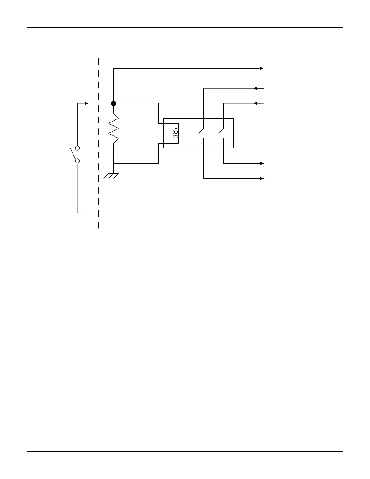
Figure 8-4
Using Model 2611A/2612A/2635A/2636A interlock
TSP-Link synchronization lines
The Series 2600A has three synchronization lines that you can use for triggering, digital I/O, and to
synchronize multiple instruments on a TSP-Link network.
Connecting to TSP-Link
The TSP-Link synchronization lines are built into TSP-Link. Use the TSP-Link connectors located
on the back of the Series 2600A. If you use the TSP-Link network, you do not have to modify your
connections. See
System Expansion (TSP-Link) for detailed information about connecting to TSP-
Link.
Using TSP-Link synchronization lines for digital I/O
Each synchronization line is an open-drain signal. When using the TSP-Link synchronization lines
for digital I/O, any node that sets the programmed line state to 0 (zero) causes all nodes to read 0
from the line state. This occurs regardless of the programmed line state of any other node.
Digital I/O bit weighting
Table 8-3 displays the bit weighting for the digital I/O lines.
To output stage
10kW
Rear panel
Chassis ground
Coil resistance
145W +/- 10%
-220V supply
+220V supply
INTERLOCK pin
(on DIGITAL I/O connector)
Read by firmware
Pin 24
Closing
Switch
Enables
200V
Operation
+5V
Pin 23