15-10 Return to Section Topics 2600AS-901-01 Rev. B / September 2008
Section 15: Communications Interfaces Series 2600A System SourceMeter® Instruments Reference Manual
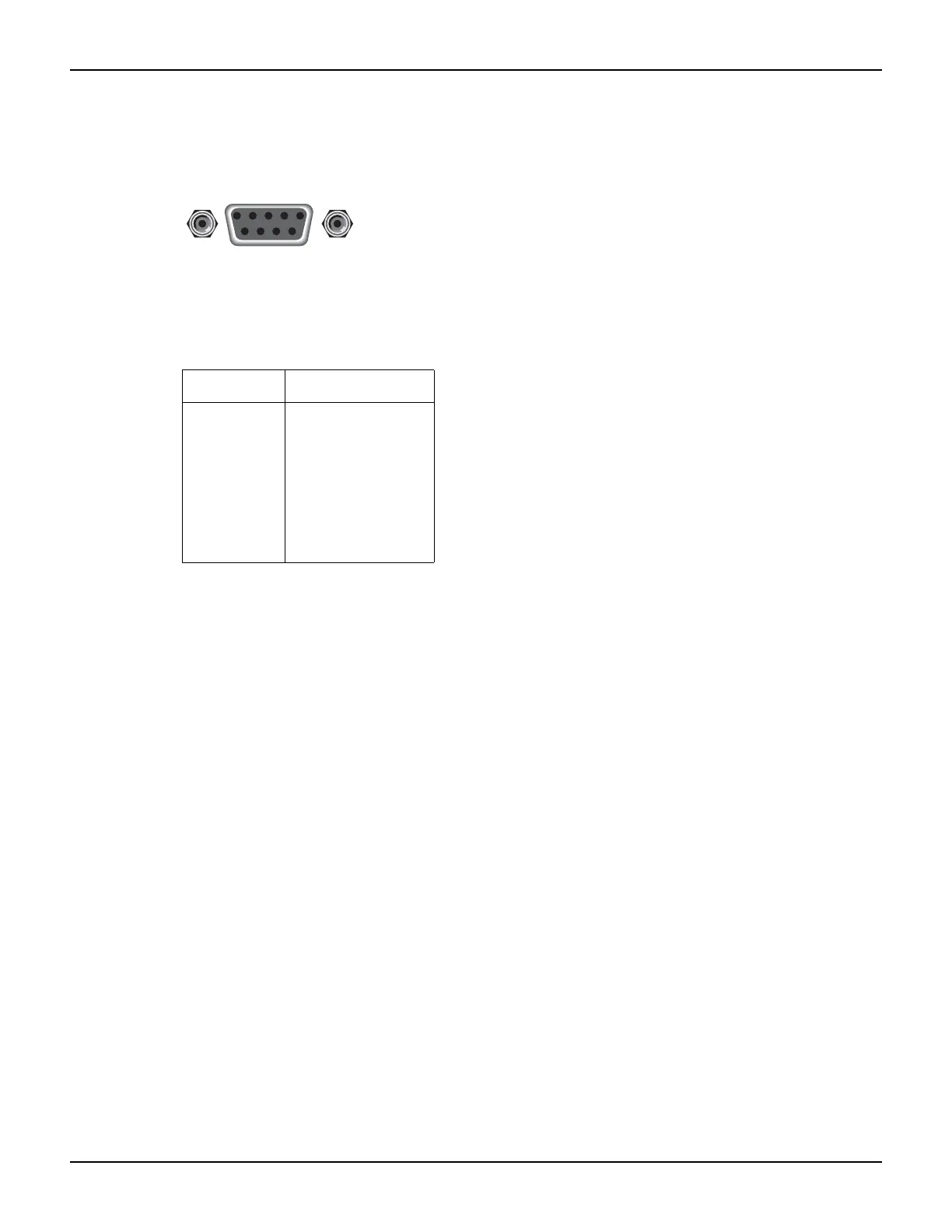
Figure 15-4
RS-232 interface connector
To enable or disable flow control, use the RS-232 configuration menu. Select HARDWARE to
enable flow control, or NONE to disable it.
RS-232 connections
The RS-232 serial port is connected to the serial port of a computer using a straight-through RS-
232 cable terminated with DB-9 connectors. Do not use a null modem cable. The serial port uses
the transmit (TXD), receive (RXD), CTS and RTS (if flow control is enabled), and signal ground
(GND) lines of the RS-232 standard.
Figure 15-4 shows the rear panel connector for the RS-232
interface, and Table 15-3 shows the pinout for the connector. The connector location is shown in
Figure 15-3.
If your computer uses a DB-25 connector for the RS-232 interface, you will need a standard cable
or adapter with a DB-25 connector on one end and a DB-9 connector on the other. An available
RS-232 cable from Keithley Instruments is listed in
Options and accessories in Section 1.
Table 15-4 provides pinout identification for the 9-pin (DB-9) or 25-pin (DB-25) serial port
connector on the computer (PC).
Table 15-3
RS-232 connector pinout
Pin number Description
1
2
3
4
5
6
7
8
9
Not used
TXD, transmit data
RXD, receive data
Not used
GND, signal ground
Not used
RTS, ready to send
CTS, clear to send
Not used
9876
54321
Rear Panel Connector
RS-232