11-6 Limit Testing
Binning control
The binning control selection determines when the testing process stops and the appropriate
binning operation occurs. The results are communicated through the Digital I/O port based on
limit test data. (See Binning systems later in this section.) There are two types of binning con-
trol for the grading mode: immediate and end.
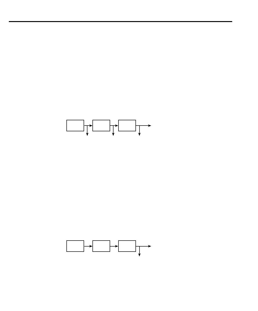
Immediate binning — Use immediate binning when you want to stop all testing after the
first failure occurs. Any pending tests will be cancelled, and the DUT will be placed in the bin
assigned to that test failure. If no failures occur, all enabled tests will be performed, and the
DUT will be placed in the assigned “pass” bin. This process is demonstrated in Figure 11-3.
Using a sweep with immediate binning lets you test different devices at different source lev-
els. For example, assume a 3-point linear sweep at 1V, 2V, and 3V step levels. The first DUT is
tested at 1V, the second DUT is tested at 2V, and the third DUT is tested at 3V.
End binning — End binning allows a sweep to finish before performing the binning opera-
tion. In the event of a failure, the first test failure determines the bin assignment. (See Figure
11-4.)
Using a sweep with end binning lets you test a device at different source levels. For exam-
ple, assume a 3-point list sweep at 1.1V, 2.2V, and 3.3V source levels. Limit testing will be per-
formed at each source level. After the completion of the three test cycles, the DUT is placed in
the appropriate bin.
Adding a scanner to the system lets you test each element of a multi-element device (i.e.,
resistor network). For example, the previous 3-point list sweep can be used to test a 3-element
resistor network. The first test cycle (using the 1.1V source level) tests the first element of the
network. The second test cycle (2.2V) tests the second element of the network, and last test
cycle (3.3V) tests the third element. After the three test cycles are finished, the resistor network
is placed in the appropriate bin.
Test1 Test2 Test3
Pass Fail Pass
Digital I/O
Pass/Fail
Notification
Figure 11-3
Immediate binning
Test1
(Pass)
Test2
(Fail)
Test3
(Pass)
Fail
Digital I/O
Notification
Figure 11-4
End binning