Performance Verification 18-5
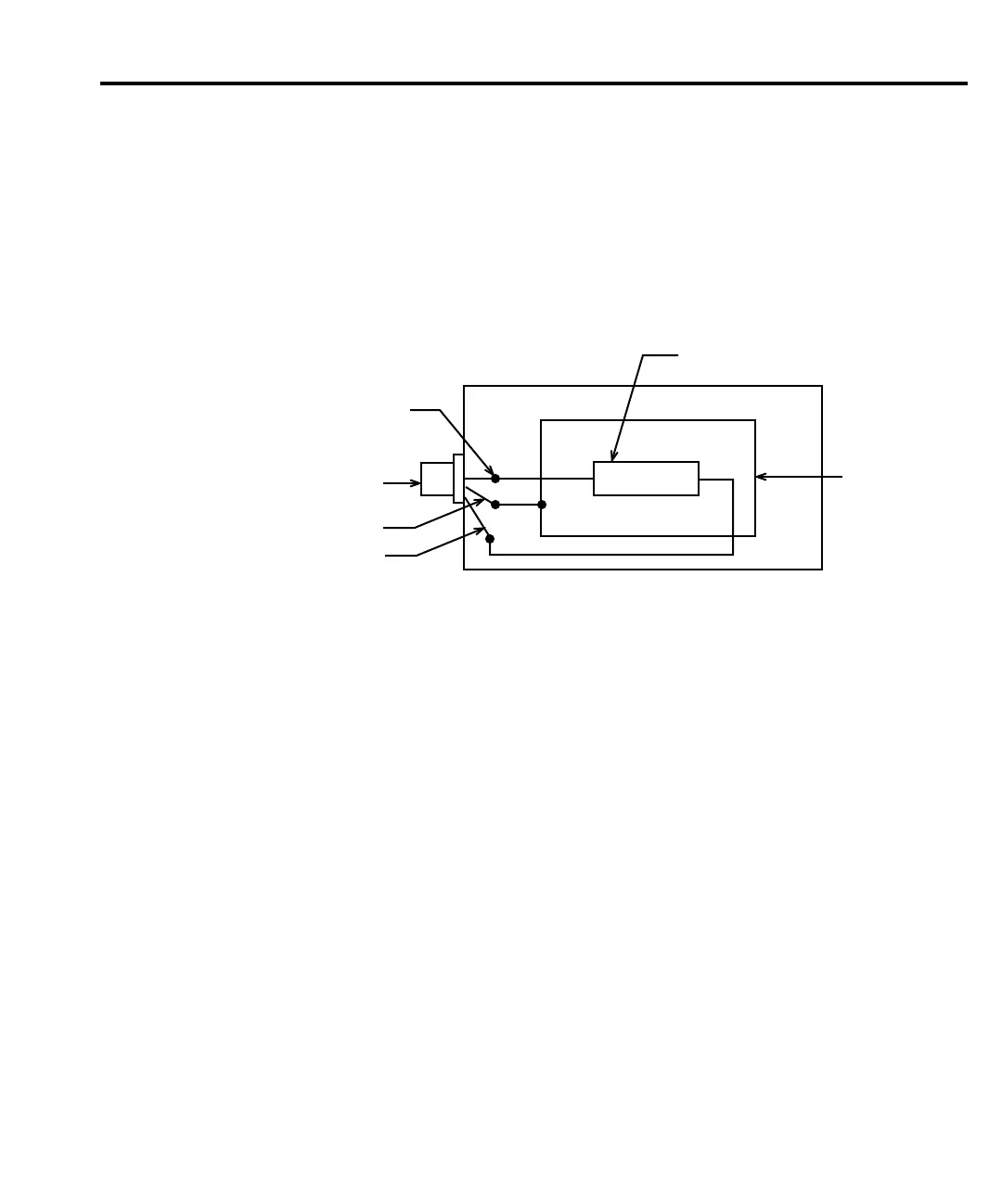
Test resistor construction
The 1TΩ and 10TΩ test resistors used to test the 2TΩ and 20TΩ resistance ranges should be
mounted in a shielded, guarded enclosure like the one shown in Figure 18-1. The resistors
should be properly characterized to the accuracy stated in Table 18-1 before use. Connect the
resistors terminals to the triax jack center conductor and outer shell. Connect the guard shield
to the triax jack inner ring.
WARNING To avoid a shock hazard, do not connect guard to an exposed shield.
Verification limits
Most of the verification reading limits stated in this section have been calculated using only
the Model 6430 one-year accuracy specifications, and most reading limits do not include test
equipment uncertainty. (However, 1pA-100nA and 2GΩ-200GΩ range limits do include the
uncertainty of the Model 5156 Electrometer Calibration Standard.) If a particular measurement
falls outside the allowable range, recalculate new limits based both on Model 6430 specifica-
tions and corresponding test equipment specifications.
Example limits calculation
As an example of how verification limits are calculated, assume you are testing the 20V DC
source range using a 20V output value. Using the Model 6430 20V range one-year accuracy
specification of ±(0.02% of output + 2.4mV offset), the calculated output limits are:
Output limits = 20V ± [(20V × 0.02%) + 2.4mV]
Output limits = 20V ± (0.004 + 0.0024)
Output limits = 20V ± 0.0064V
Output limits = 19.9936V to 20.0064V
Center
Conductor
Triax Jack
Inner Ring
Shell
Guard
Shield
1TΩ or 10TΩ
Resistor
Figure 18-1
Test resistor
construction