F-4 Measurement Considerations
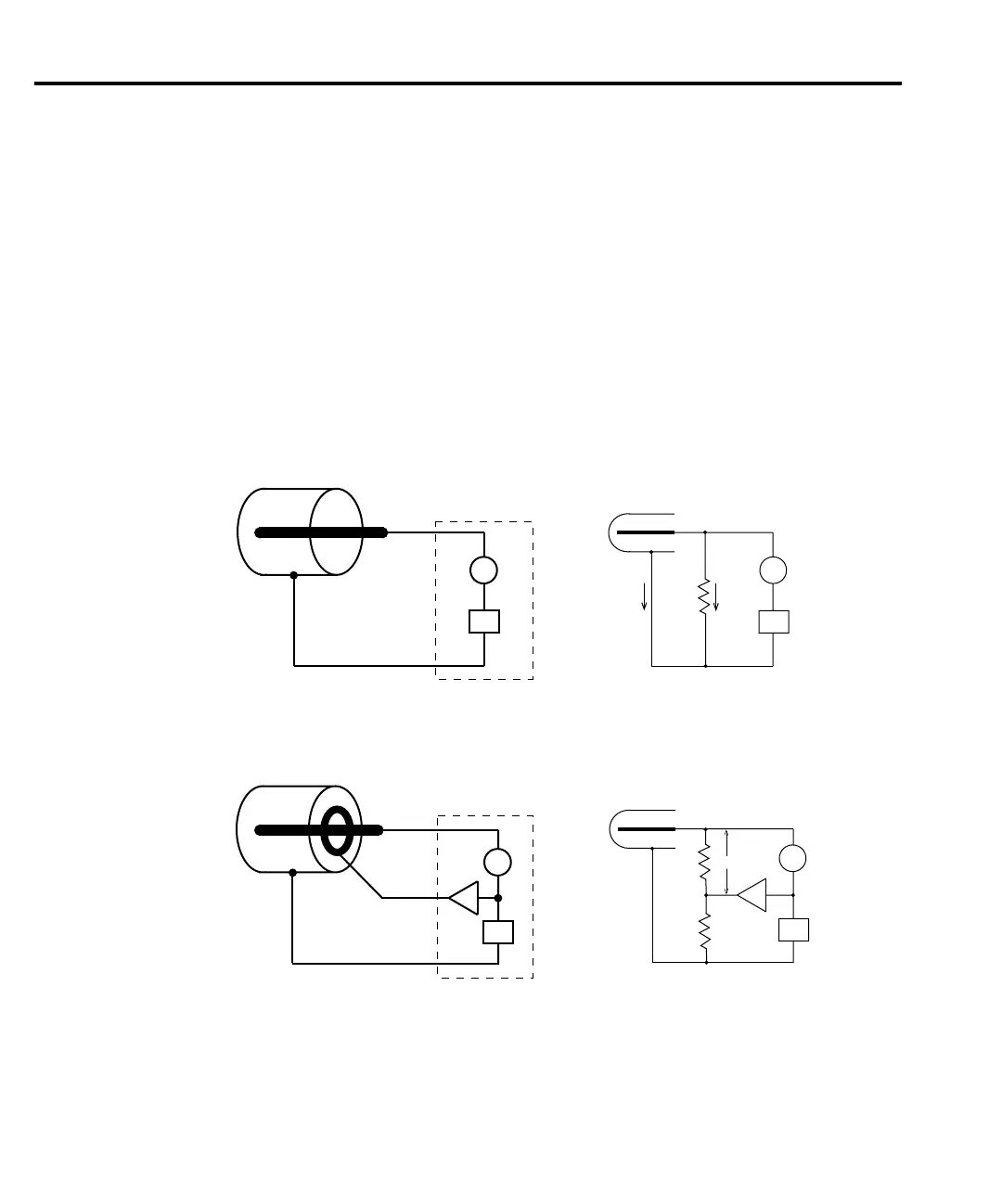
An example of guarding as applied to an ionization chamber is shown in Figure F-2. An
unguarded ionization chamber and the corresponding equivalent circuit are shown in
Figure F-2A. The equivalent circuit shows that the full bias voltage appears across the insulator
leakage resistance (R
L
) and thus, a leakage current (I
L
) will be added to the measured ion cur-
rent (I
M
= I
C
+ I
L
). The leakage resistance is primarily due to the insulator of the ionization
chamber.
In Figure F-2B, a metal guard ring is added to the ionization chamber. This guard ring is
connected to the driven guard of the Remote PreAmp. This circuit splits the leakage resistance
into two parts; R
L1
and R
L2
. The driven guard is at almost the same voltage potential as output
HI. The voltage difference is <1mV, and is known as the voltage burden of the Remote
PreAmp. Since the top and bottom of R
L1
are at nearly the same potential, no significant cur-
rent will flow through it.
In a similar manner, guarding may also be necessary to prevent leakage current in test fix-
tures. See Cable guard and Figure 5-11 in Section 5 for details.
In/Out
HI
In/Out
LO
Remote
PreAmp
IM
VS
RL IL
IC
In/Out
HI
Remote
PreAmp
Guard
In/Out
LO
IM
VS
IM
VS
x1
IM
VS
x1
RL1
RL2
<100µV
A. Unguarded ionization chamber
B. Guarded ionization chamber
Equivalent Circuit
Equivalent Circuit
Figure F-2
Guarding an
ionization
chamber