12-6 Digital I/O Port, Interlock, and Output Configuration
Safety interlock
The Digital I/O Port provides an interlock line for use with a test fixture interlock switch.
When properly used, the OUTPUT of the SourceMeter will turn OFF when the lid of the test
fixture is opened. See Connections in Section 2 for important safety information when using
the test fixture interlock.
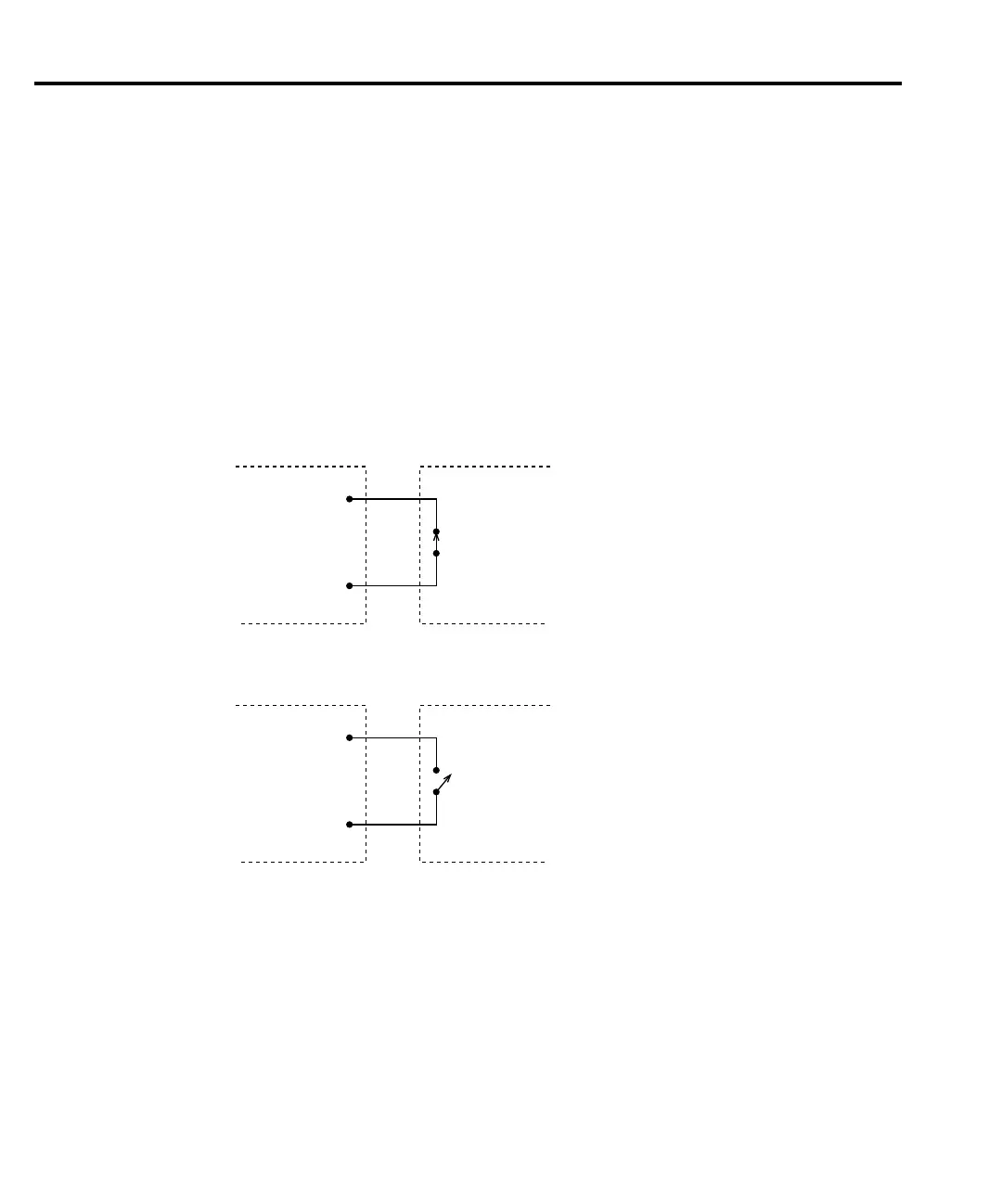
When the interlock is enabled (see Front panel output configuration later in this section), the
output of the SourceMeter cannot be turned on unless the interlock line is pulled low through a
switch to ground as shown in Figure 12-4A. If the lid of the test fixture opens (Figure 12-4B),
the switch opens, and the interlock line goes high turning the OUTPUT of the SourceMeter
OFF (high impedance). The output can only be turned back on by first closing the lid of the test
fixture and then pressing the OUTPUT ON/OFF key.
NOTE Interlock can be driven by Digital I/O. Allow 100µs settling and response time. The
Digital I/O lines are open-collector, edge-sensitive and signals should be de-
bounced to avoid erratic operation.
/Interlock
(pin 8)
GND
(pin 5 or 9)
Interlock Switch
(Lid Closed)
Interlock-
Digital I/O
SourceMeter Test Fixture
A. SourceMeter OUTPUT can be turned on.
/Interlock
(pin 8)
GND
(pin 5 or 9)
Interlock Switch
(Lid Open)
SourceMeter Test Fixture
B. SourceMeter OUTPUT turns off.
Interlock-
Digital I/O
Figure 12-4
Using test fixture
interlock