Remote Operations 13-5
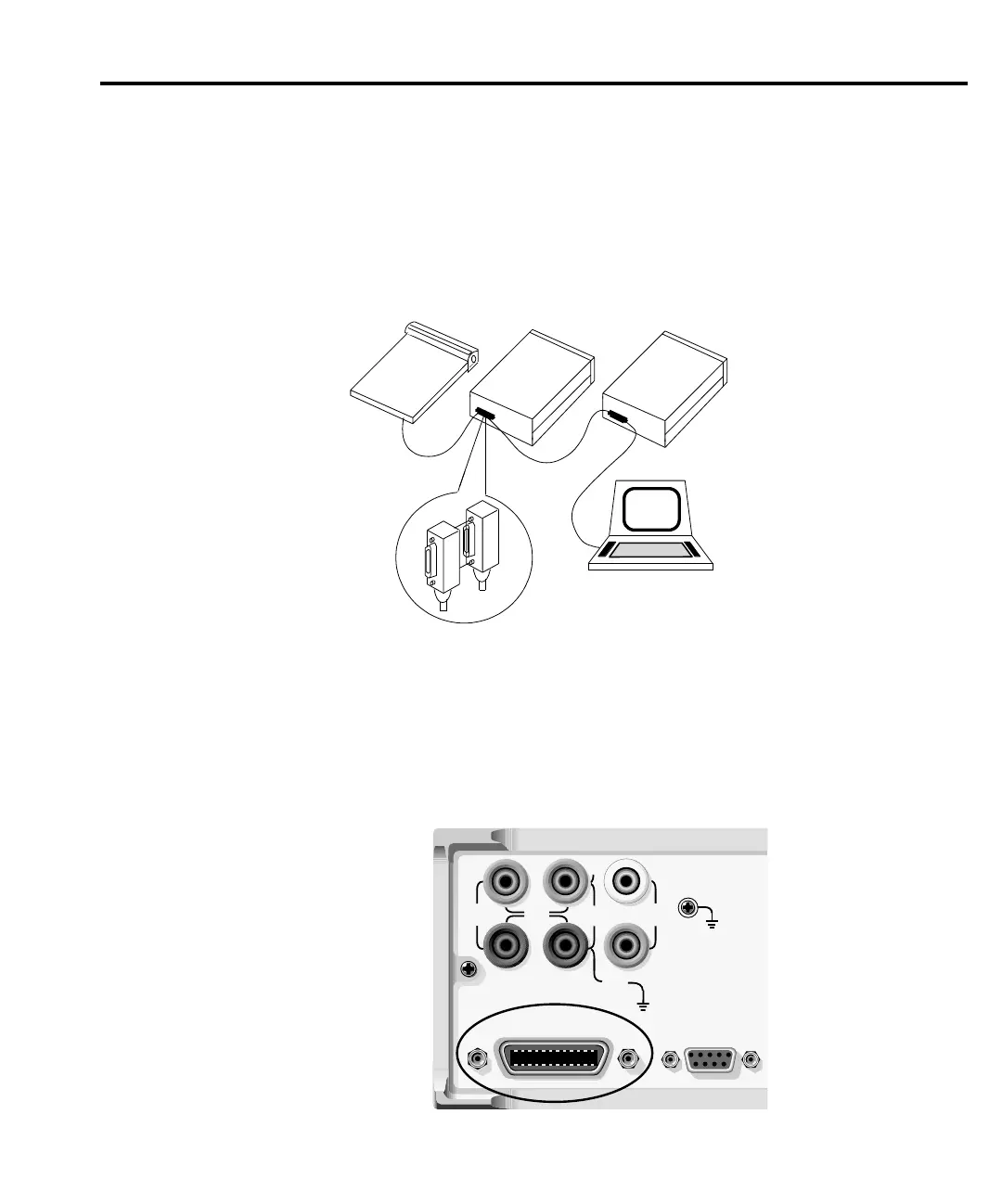
Figure 13-2 shows a typical connecting scheme for a multi-unit test system.
To avoid possible mechanical damage, stack no more than three connectors on any one unit.
NOTE To minimize interference caused by electromagnetic radiation, use only shielded
IEEE-488 cables. Available shielded cables from Keithley are Models 7007-1 and
7007-2.
To connect the SourceMeter to the IEEE-488 bus, follow these steps:
1. Line up the cable connector with the connector located on the rear panel. The connector
is designed so it will fit only one way. Figure 13-3 shows the location of the IEEE-488
connector.
2. Tighten the screws securely, making sure not to overtighten them.
Instrument
Controller
Instrument Instrument
gure
-
EEE-488 connections
INPUT/
OUTPUT
42V
PEAK
250V
PEAK
4-WIRE
SENSE
HI
LO
IEEE-488
(ENTER IEEE ADDRESS
WITH FRONT PANEL MENU)
250V
PEAK
5V
PEAK
5V
PEAK
5V
PK
V, Ω,
GUARD
GUARD
SENSE
WARNING:NO INTERNAL OPERATOR SERVICAB
WARNING:NO INTERNAL OPERATOR SERVICAB
CAUTION:FOR CONTINUED PROTECTION AGAINST FIR
CAUTION:FOR CONTINUED PROTECTION AGAINST FIR
RS232
Figure 13-3
IEEE-488 connector location