1-10 Getting Started
High voltage differentials — Exceeding the high voltage differentials (42V peak and 250V
peak) could damage the instrument and create a shock hazard.
Remote PreAmp connector:
REMOTE PREAMP Connect the Remote PreAmp to the mainframe using the supplied
preamp cable (CA-176-1D).
Interlock and digital input/output port:
INTERLOCK — DIGITAL I/O Male DB-9 connector for digital output lines, interlock, and
component handler signals.
Power module:
Contains the AC line receptacle and the power line fuse.
Trigger link connector:
TRIGGER LINK 8-pin micro-DIN connector for sending and receiving trigger pulses.
Use a trigger link cable or adapter, such as Models 8501-1, 8501-2,
8502, 8504.
RS-232 connector:
RS-232 Connector for RS-232 remote operation. Use a straight through (not
null modem) DB-9 cable such as Keithley Model 7009-5.
GPIB connector:
IEEE-488 INTERFACE Connector for GPIB remote operation. Use a shielded cable
(Model 7007-1 or 7007-2).
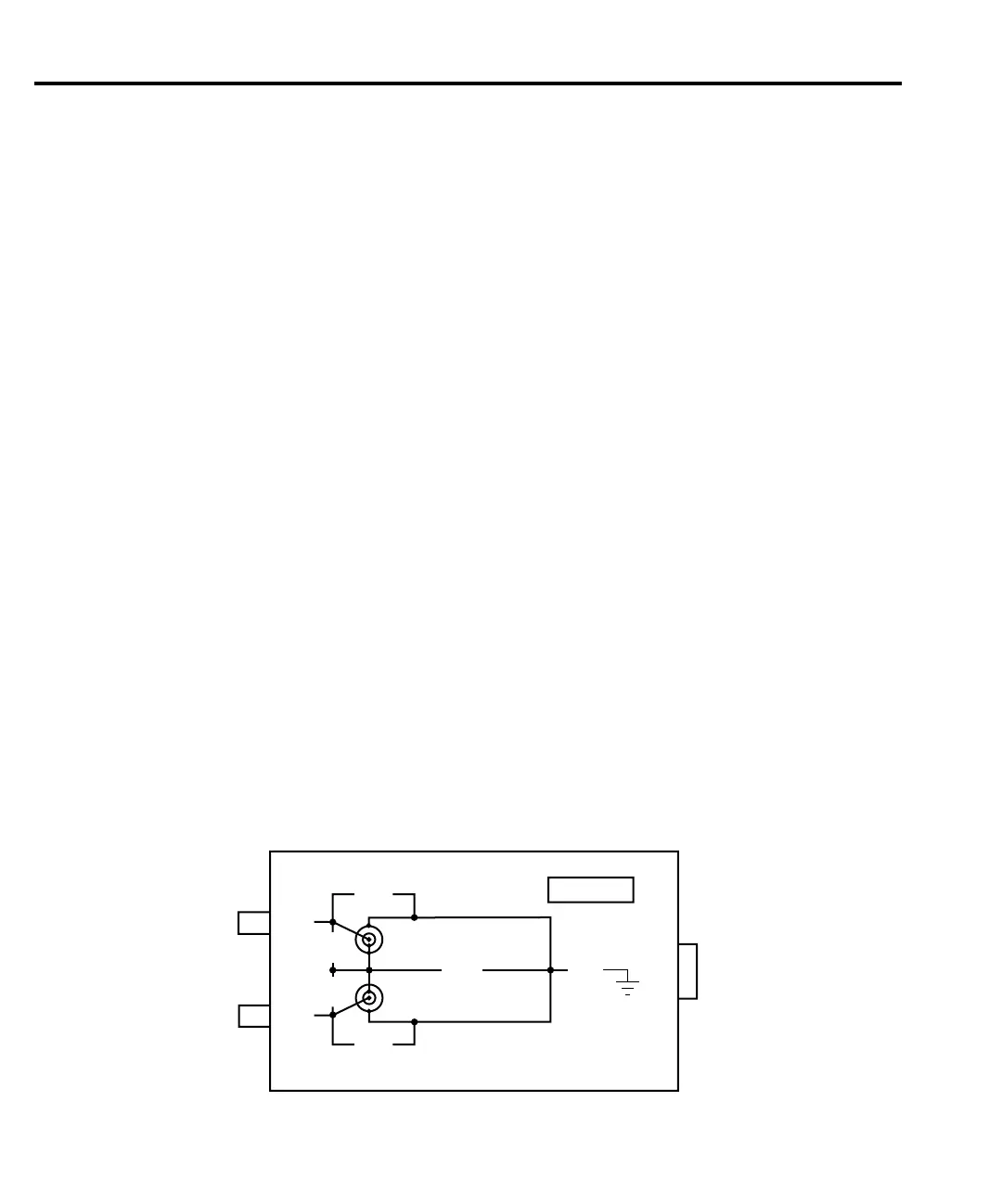
Remote PreAmp summary
The Remote PreAmp is shown in Figure 1-3 and terminal identification for the IN/OUT
HIGH and SENSE triax connectors is provided in Figure 1-4.
SENSE
KEITHLEY
250V
Peak
HI
HI
40V
Peak
40V
Peak
GUARD
250V
Peak
250V
Peak
IN/OUT
LO
42V
Peak
REMOTE Preamp
MAINFRAME
IN/OUT
HIGH
Figure 1-3
Remote preamp