EasyManua.ls Logo

Keithley 6430 User Manual

Keithley 6430
558 pages
To Next Page IconTo Next Page
To Previous Page IconTo Previous Page
Page #246 background imageLoading...
Page #246 background image
11-20 Limit Testing
Limit test programming example
Diode breakdown voltage test is an example that readily lends itself to pass/fail analysis.
This test veries the reverse and often the forward voltage at which the device begins to show a
large deviation in current for a small deviation in voltage. The test is performed by sourcing a
specied current level and then measuring the resulting voltage drop. The voltage drop is then
compared with one set of limits to determine if the diode passes, or fails and should be dis-
carded. Voltage measurements for failing diodes are also compared against a more restricted
range of limits to determine if they should be routed to QA (Quality Assurance) for further
analysis.
Test parameters for this test include:
Source Function: current
Sense Function: voltage
Source Current: 100mA
Source Delay: 100ms
Limit 2 Upper Value: 0.85V
Limit 2 Lower Value: 0.75V
Limit 3 Upper Value: 0.82V
Limit 3 Lower Value: 0.78V
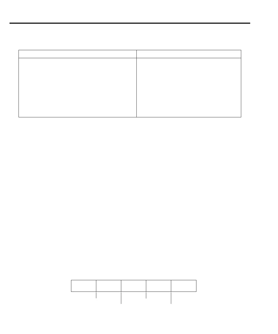
Figure 11-11 demonstrates graphically how parts are sorted. Diodes with a voltage between
0.78V and 0.82V are considered good and will pass the limits test. Diodes that test with a
slightly wider voltage range are routed to QA for analysis, while those with the largest voltage
tolerance will be discarded.
Command* Description*
:SOURce2:BSIZe <n> Set Digital I/O port bit size (n = 3 or 4).
:SOURce2:TTL <NRf> | <NDN> Set I/O port bit pattern (NRf | NDN = pattern).
:SOURce2:TTL:ACTual? Query bit pattern on digital output port.
:SOURce2:TTL4:MODE <name> Set Digital I/O line 4 mode (name = EOTest or
BUSY).
:SOURce2:TTL4:BSTate <state> Set BUSY and EOT polarity (HI or LO).
:SOURce2:CLEar Clear digital output lines.
:SOURce2:CLEar:AUTO <state> Enable/disable I/O port auto clear (state = ON or
OFF).
:SOURce2:CLEar:AUTO:DELay <n> Set auto-clear delay (n = delay).
*LIMitX = LIMit2, LIMit3, LIMit5 through LIMit12.
Table 11-1 (cont.)
Limit commands
Bad Diode,
Discard
Bad Diode,
to QA
Good
Diode
Bad Diode,
to QA
Bad Diode,
Discard
Low Limit 2
(0.75V)
Low Limit 3
(0.78V)
Upper Limit 3
(0.82V)
Upper Limit 2
(0.85V)
Figure 11-11
Diode pass/fail limits

Table of Contents

Other manuals for Keithley 6430

Question and Answer IconNeed help?

Do you have a question about the Keithley 6430 and is the answer not in the manual?

Keithley 6430 Specifications

General IconGeneral
TypeSub-Femtoamp Remote SourceMeter
Compliance Voltage200 V
Maximum Output Voltage200 V
Maximum Output Current100 mA
Compliance LimitProgrammable
InterfaceGPIB, RS-232
Input Impedance>10^14 Ω

Summary

Safety Precautions

3 Basic Source-Measure Operation

Basic Source-Measure Procedure

Details setup for source-measure operations: function, values, limits, and output control.

5 Source-Measure Concepts

Compliance limit

Discusses compliance limits, values, and determination.

Operating boundaries

Covers voltage/current boundaries for source, sink, I-source, V-source, and source-measure modes.

6 Range, Digits, Speed, and Filters

Range and digits

Discusses available ranges, limits, manual/autoranging, and display resolution.

Filters

Provides information on 3-stage filtering to reduce reading noise.

7 Relative and Math

Math Operations

Details math (FCTN) operations: power, offset ohms, varistor, etc.

9 Sweep Operation

Configuring and Running a Sweep

Discusses setup, configuration, delay setting, and performing sweeps.

10 Triggering

Trigger Model

Discusses trigger model, layers, event detection, delay, and device action.

Configuring Triggering

Details how to configure various triggering aspects.

Remote Triggering

Details remote trigger model, commands, and basic triggering example.

11 Limit Testing

Types of Limits

Discusses three limit types: compliance, coarse, fine; summarizes grading and sorting modes.

Configuring and Performing Limit Tests

Describes configuration for limit tests and typical test procedure.

12 Digital I/O Port, Interlock, and Output Configuration

Safety Interlock

Describes using Digital I/O Port as a safety interlock.

14 Status Structure

Status Byte and Service Request (SRQ)

Explains programming Status Byte for SRQs and using serial poll to detect SRQs.

15 Common Commands

Command Summary

Lists IEEE-488.2 common commands used by the SourceMeter.

Command Reference

Provides detailed reference for common commands, excluding status structure.

16 SCPI Signal-Oriented Measurement Commands

Configuring Measurement Function

Provides detailed info on commands to configure measurement function.

Acquiring Readings

Describes commands to acquire post-processed readings, trigger, acquire, and single measurement.

17 SCPI Command Reference

18 Performance Verification

Performing the Verification Test Procedures

Details restoring factory defaults, setting ranges, and output values.

Mainframe Verification

Covers procedures to verify mainframe accuracy alone.

19 Calibration

Mainframe Calibration

Includes procedures to calibrate the mainframe without the Remote PreAmp.

20 Routine Maintenance

Line Fuse Replacement

Covers procedure and part numbers for replacing the line fuse.

F Measurement Considerations

Floating measurement safety concerns

Discusses safety concerns for measurements up to 42V above chassis ground.

Leakage currents and guarding

Explains reducing leakage currents using insulators, humidity control, and guarding.

Related product manuals