EasyManua.ls Logo

Keithley 6430 User Manual

Keithley 6430
558 pages
To Next Page IconTo Next Page
To Previous Page IconTo Previous Page
Page #236 background imageLoading...
Page #236 background image
11-10 Limit Testing
Binning systems
The SourceMeter can be used with a component handler to perform binning operations on
DUT packages. With this system, you can test single-element devices (i.e., resistor). Adding a
scanner to the system allows binning operations on multiple-element DUT packages. See Limit
test programming example at the end of this section.
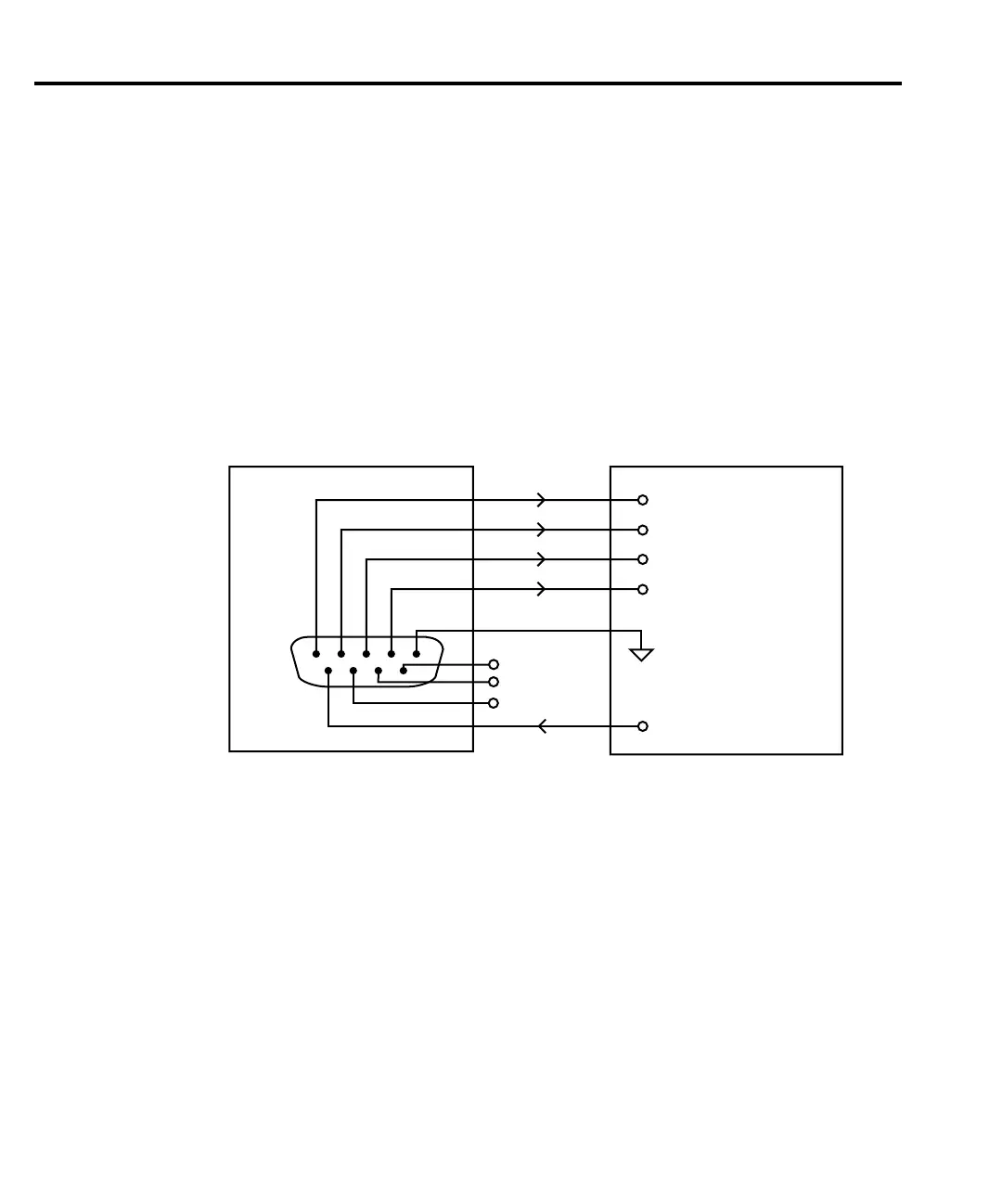
Handler interface
The SourceMeter is interfaced to a handler via the Digital I/O port as shown in Figure 11-6.
The I/O port has four lines for output signals and one line for input signals. The output lines are
used to send the test pass/fail signal(s) to the handler to perform the binning operation.
Digital I/O connector
These digital I/O lines are available at the DB-9 Digital I/O connector on the rear panel of
the SourceMeter. A custom cable using a standard female DB-9 connector is required for con-
nection to the SourceMeter. See Digital I/O port in Section 12 for more information.
Digital output lines
The four output lines output a specic bit pattern based on the pass/fail results of the various
limit tests. (See Types of limits earlier in this section). In the 3-bit output mode, Line 4 can also
be used either as an EOT (End of Test) or BUSY signal depending on the END OF TEST
mode. (See Configuring limit tests later in this section.)
SourceMeter
Handler
Out 1
Out 2
Out 3
Out 4
Gnd
Dig I/O
1
6
5
9
+5V
Input (SOT)
Line 1
Line 2
Line 3
Line 4 (EOT or BUSY)
SOT Strobe Line
/INT
Gnd
Figure 11-6
Handler interface
connections

Table of Contents

Other manuals for Keithley 6430

Question and Answer IconNeed help?

Do you have a question about the Keithley 6430 and is the answer not in the manual?

Keithley 6430 Specifications

General IconGeneral
TypeSub-Femtoamp Remote SourceMeter
Compliance Voltage200 V
Maximum Output Voltage200 V
Maximum Output Current100 mA
Compliance LimitProgrammable
InterfaceGPIB, RS-232
Input Impedance>10^14 Ω

Summary

Safety Precautions

3 Basic Source-Measure Operation

Basic Source-Measure Procedure

Details setup for source-measure operations: function, values, limits, and output control.

5 Source-Measure Concepts

Compliance limit

Discusses compliance limits, values, and determination.

Operating boundaries

Covers voltage/current boundaries for source, sink, I-source, V-source, and source-measure modes.

6 Range, Digits, Speed, and Filters

Range and digits

Discusses available ranges, limits, manual/autoranging, and display resolution.

Filters

Provides information on 3-stage filtering to reduce reading noise.

7 Relative and Math

Math Operations

Details math (FCTN) operations: power, offset ohms, varistor, etc.

9 Sweep Operation

Configuring and Running a Sweep

Discusses setup, configuration, delay setting, and performing sweeps.

10 Triggering

Trigger Model

Discusses trigger model, layers, event detection, delay, and device action.

Configuring Triggering

Details how to configure various triggering aspects.

Remote Triggering

Details remote trigger model, commands, and basic triggering example.

11 Limit Testing

Types of Limits

Discusses three limit types: compliance, coarse, fine; summarizes grading and sorting modes.

Configuring and Performing Limit Tests

Describes configuration for limit tests and typical test procedure.

12 Digital I/O Port, Interlock, and Output Configuration

Safety Interlock

Describes using Digital I/O Port as a safety interlock.

14 Status Structure

Status Byte and Service Request (SRQ)

Explains programming Status Byte for SRQs and using serial poll to detect SRQs.

15 Common Commands

Command Summary

Lists IEEE-488.2 common commands used by the SourceMeter.

Command Reference

Provides detailed reference for common commands, excluding status structure.

16 SCPI Signal-Oriented Measurement Commands

Configuring Measurement Function

Provides detailed info on commands to configure measurement function.

Acquiring Readings

Describes commands to acquire post-processed readings, trigger, acquire, and single measurement.

17 SCPI Command Reference

18 Performance Verification

Performing the Verification Test Procedures

Details restoring factory defaults, setting ranges, and output values.

Mainframe Verification

Covers procedures to verify mainframe accuracy alone.

19 Calibration

Mainframe Calibration

Includes procedures to calibrate the mainframe without the Remote PreAmp.

20 Routine Maintenance

Line Fuse Replacement

Covers procedure and part numbers for replacing the line fuse.

F Measurement Considerations

Floating measurement safety concerns

Discusses safety concerns for measurements up to 42V above chassis ground.

Leakage currents and guarding

Explains reducing leakage currents using insulators, humidity control, and guarding.

Related product manuals