EN UG-020 Link 6 user guide r1.0 224
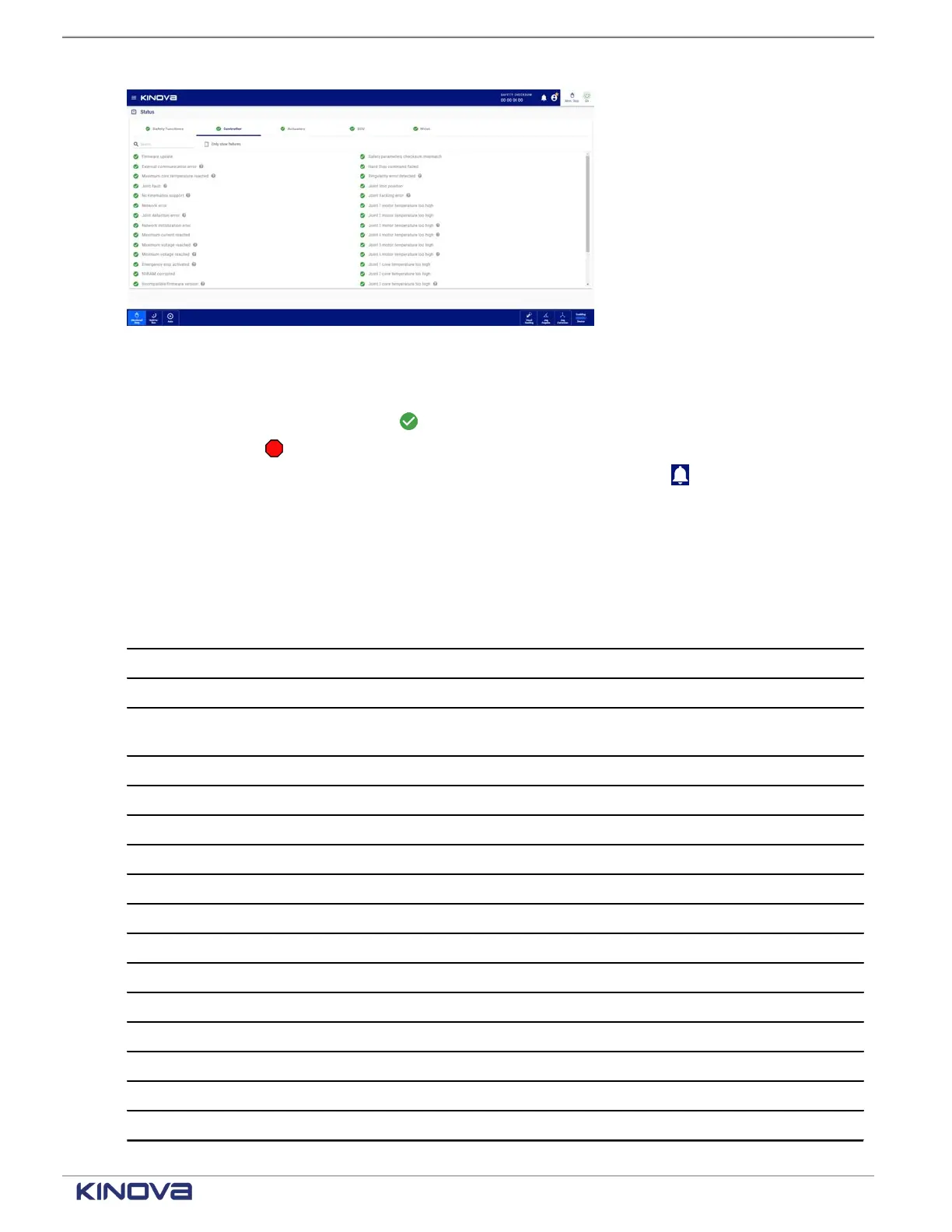
Figure 189: Status page of the controller
Each controller status displays one of its two states.
•
A green circle with a checkmark ( ) beside the status indicates that controller status is fine.
•
A red octagon ( ) beside the name of the controller status indicates that status has errors;
more information may be available by tapping the Notifications icon ( ).
The Controller pane displays all the status that are being monitored, including internal variables.
Some of the internal variables cannot be accessed by users; the variables may be associated
with hardware problems.Contact support at support@kinova.ca.
Table 89: Listing of arm status
Status Not addressable by users Addressable by users
Firmware update failure x
External communication error x
Maximum core temperature
reached
x
Joint fault x
No kinematics support x
Network error x
Joint detection error x
Network initialization error x
Maximum current reached x
Maximum voltage reached x
Minimum voltage reached x
Emergency stop activated x
NVRAM corrupted x
Incompatible firmware version x
Stop triggered x
Protection zone collision deteced x
+1 514-277-3777 kinovarobotics.com
© 2022 Kinova inc. All rights reserved.