EN UG-020 Link 6 user guide r1.0 26
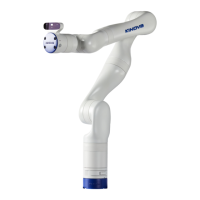
Figure 20: Input and output connectors are on the controller behind the side panel
The controller uses 12 VDC to power the internal computer units, which include Safety Control
Unit (SCU), Main Processing Unit (MPU), I/O module, and optional GPU. It uses 48 VDC to power
the arm.
Connect the controller to a power supply from its back.
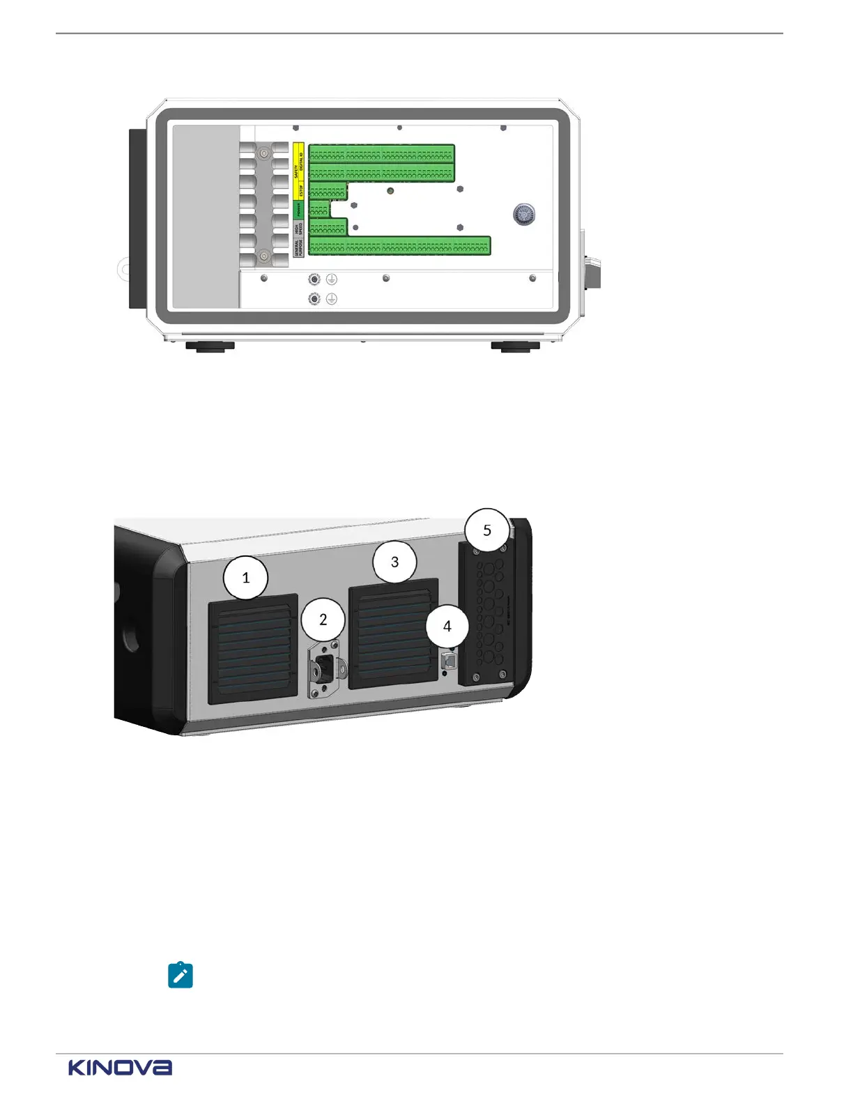
Figure 21: Back of controller
1 Fan-powered air exhaust
Electrical input for alternating current (AC) power2
Unplug the AC power cord from the controller and use the brackets around the input to lock
access to the power input whenever you perform maintenance on the robot.
3 Fanless air intake
RJ45 Ethernet connector
4
Use the Ethernet connector at the back of the controller to connect to the network.
Note: Alternatively, use the Ethernet connector on the front of the controller.
5 Entry plate for I/O connectors
+1 514-277-3777 kinovarobotics.com
© 2022 Kinova inc. All rights reserved.
 Loading...