COMMON RAIL SYSTEM
07-CR-E5,07-CR-TE5,07-CR-TIE5, DM
1-S116
9Y3200007CRS0152US0
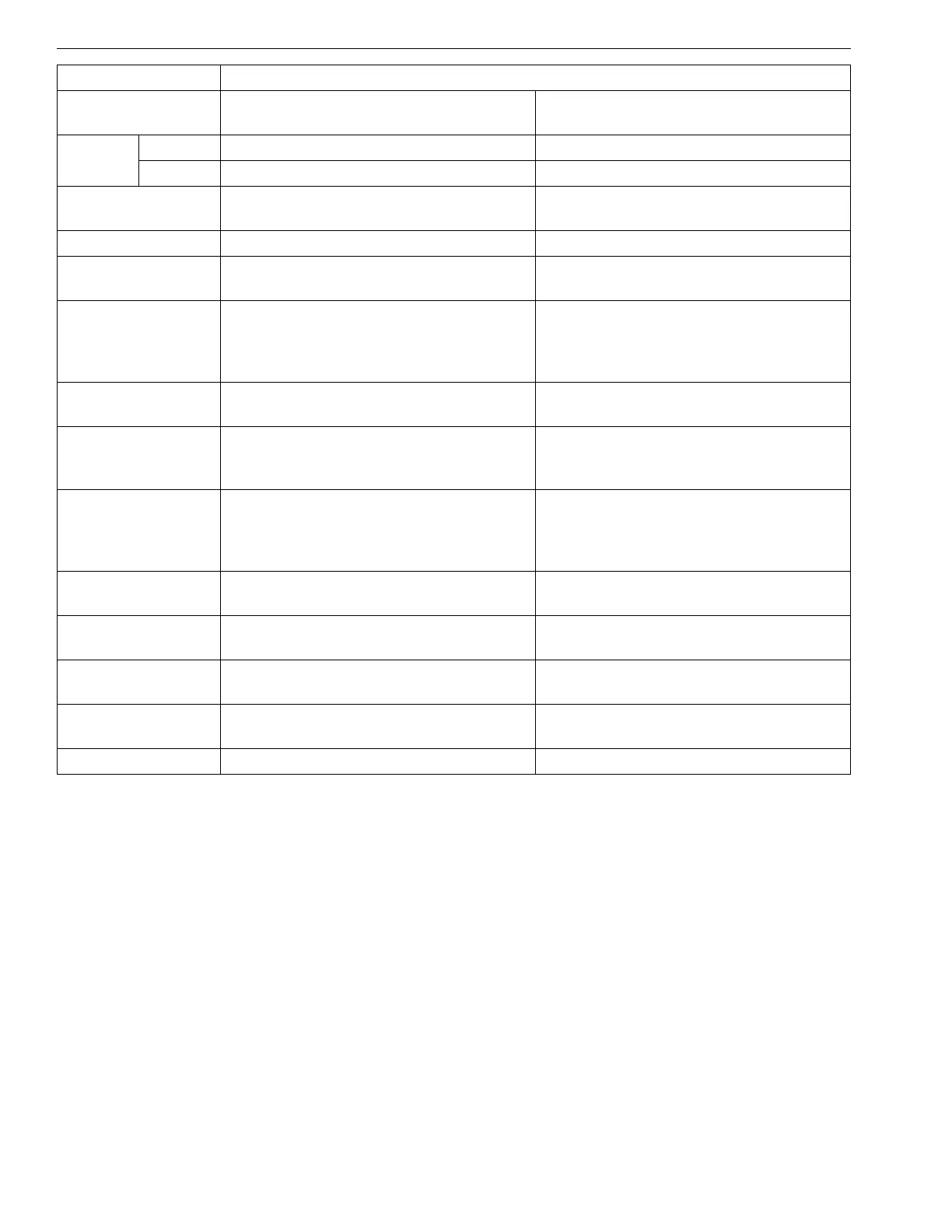
Name Differential pressure sensor abnormality
ISO 14229
P-Code
P2454 P2455
J1939-73
SPN 3251 3251
FMI 43
SPN Name
SAE J1939 Table C1
Aftertreatment 1 Diesel Particulate Filter
Differential Pressure
Aftertreatment 1 Diesel Particulate Filter
Differential Pressure
DTC Name Differential pressure sensor 1: Low Differential pressure sensor 1: High (PCD)
Detection item
• Ground short circuit of sensor / harness • Open circuit or +B short circuit of sensor
/ harness
DTC Set
Preconditions
• Battery voltage is normal
• Sensor supply voltage VCC# is normal
• Starter Switch signal (Engine ECU: V12
terminal) is not activated
• Battery voltage is normal
• Sensor supply voltage VCC# is normal
• Starter Switch signal (Engine ECU: V12
terminal) is not activated
DTC set parameter
• Differential pressure sensor voltage:
0.21 V or less
• Differential pressure sensor voltage: 4.7
V or more
Time to action or
number of error
detection
• 2.8 sec. or more • 2.8 sec. or more
Limp Home Action
by engine ECU
(system action)
• 0 kPa (0.0 kgf/cm
2
, 0.0 psi) [default
value]
• Output limitation: Approximately 75 % of
normal condition
• 0 kPa (0.0 kgf/cm
2
, 0.0 psi) [default
value]
• Output limitation: Approximately 75 % of
normal condition
Behaviour During
Malfunction
•None •None
Engine Warning
Light
• ON • ON (Blinking)
Recovery from
error
• Key switch turn OFF • Diagnostic counter = zero
Delay time for
recovery
––
Remark •PCD