COMMON RAIL SYSTEM
07-CR-E5,07-CR-TE5,07-CR-TIE5, DM
1-S162
9Y3200007CRS0203US0
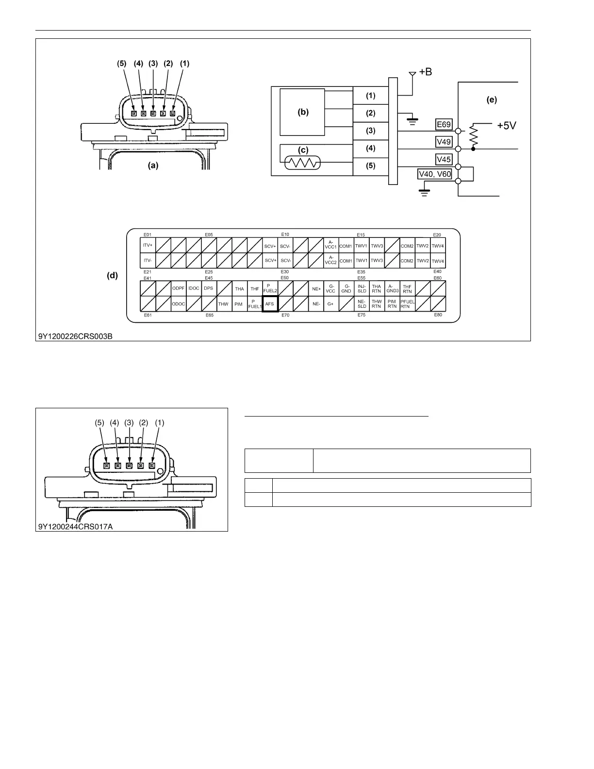
1. Measure the Sensor Terminal Voltage
1. Move the key switch from the OFF to the ON position, and
measure the voltage between sensor terminals 1 and 2.
9Y3200007CRS0204US0
(1) Terminal Power (+12 V)
(2) Terminal Ground
(3) Terminal AFS
(4) Terminal IATS
(5) Terminal A-GND10
(a) Pin Assignment
(b) Mass Air Flow (MAF) Sensor
(c) Intake Air Temperature
Sensor (Built-in MAF)
(d) Engine ECU Connector 1
(Engine Side)
(e) Engine ECU
Service
specification
Approx. 10 to 16 V
OK Go to "2. DTC Judgment".
NG Replace the wiring harness, or replace the sensor
(1) Terminal Power (+12 V)
(2) Terminal Ground
(3) Terminal AFS
(4) Terminal IATS
(5) Terminal A-GND10