COMMON RAIL SYSTEM
07-CR-E5,07-CR-TE5,07-CR-TIE5, DM
1-S182
9Y3200007CRS0245US0
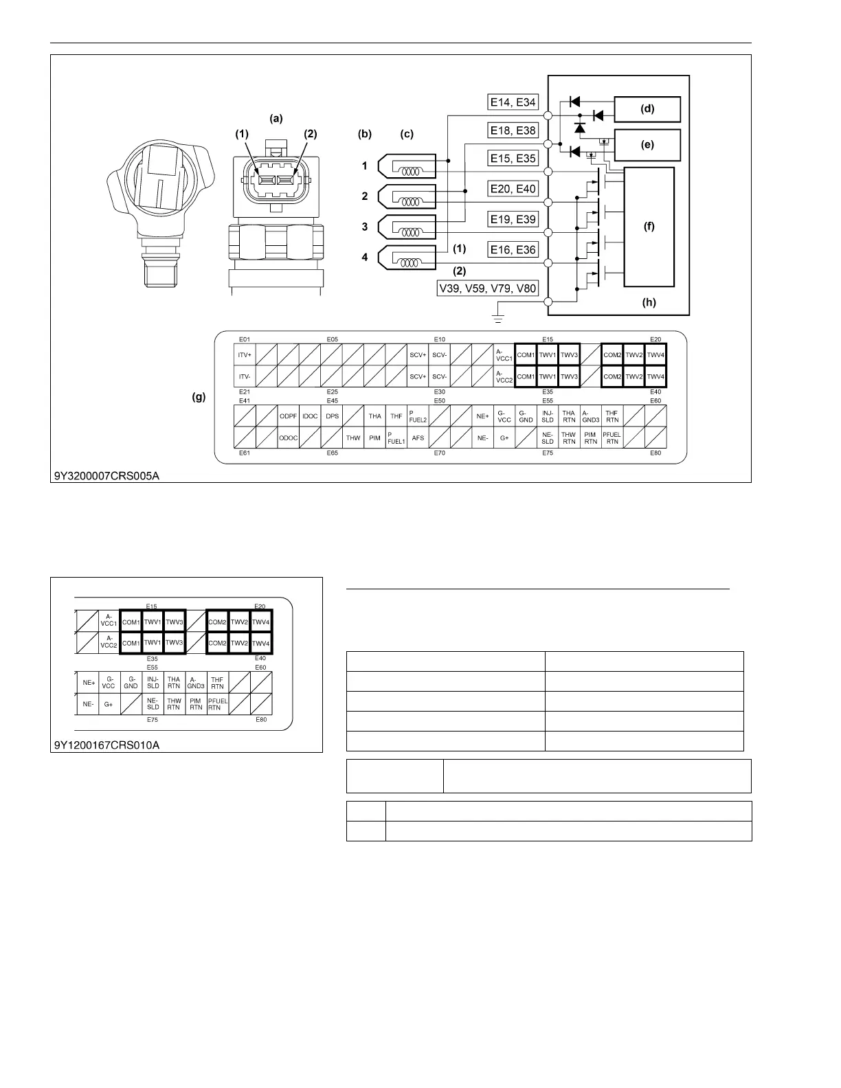
1. Measure the Resistance Between Engine ECU Terminals
1. Place the key switch in the OFF position, unplug the engine
ECU wiring harness connector from the socket, and measure
the resistance each terminal of the connector.
9Y3200007CRS0246US0
(1) Terminal COMMON
(2) Terminal TWV
(a) Pin Assignment
(b) Engine Cylinder No.
(c) Injectors
(d) Constant Amperage Circuit
(e) High Voltage Generation
Circuit
(f) Control Circuit
(g) Engine ECU Connector 1
(Engine Side)
(h) Engine ECU
Engine cylinder / TWV number Measurement terminal
No. 1 cylinder / TWV1 E14, E34 ←→ E15, E35
No. 3 cylinder / TWV2 E18, E38 ←→ E19, E39
No. 4 cylinder / TWV3 E14, E34 ←→ E16, E36
No. 2 cylinder / TWV4 E18, E38 ←→ E20, E40
Service
specification
1.5 Ω or lower
OK Go to "2. Check the DTC".
NG Go to "4. Measure the Resistance Between Injector Terminals".
 Loading...


