COMMON RAIL SYSTEM
07-CR-E5,07-CR-TE5,07-CR-TIE5, DM
1-S183
2. Check the DTC
1. Plug the engine ECU connector into socket, and start the
engine.
2. Clear the DTCs that occurred previously, and check the
currently existing trouble.
9Y3200007CRS0247US0
3. Check the Connector and Wiring Harnesses for Poor Contact
1. Set the key switch to the OFF position, and check the wiring
harness connectors and engine ECU pins for incorrect
connection, deformation, poor contact or other defects.
• Intermediate connector and wiring harness in head cover
should be checked, they are possible cause.
9Y3200007CRS0248US0
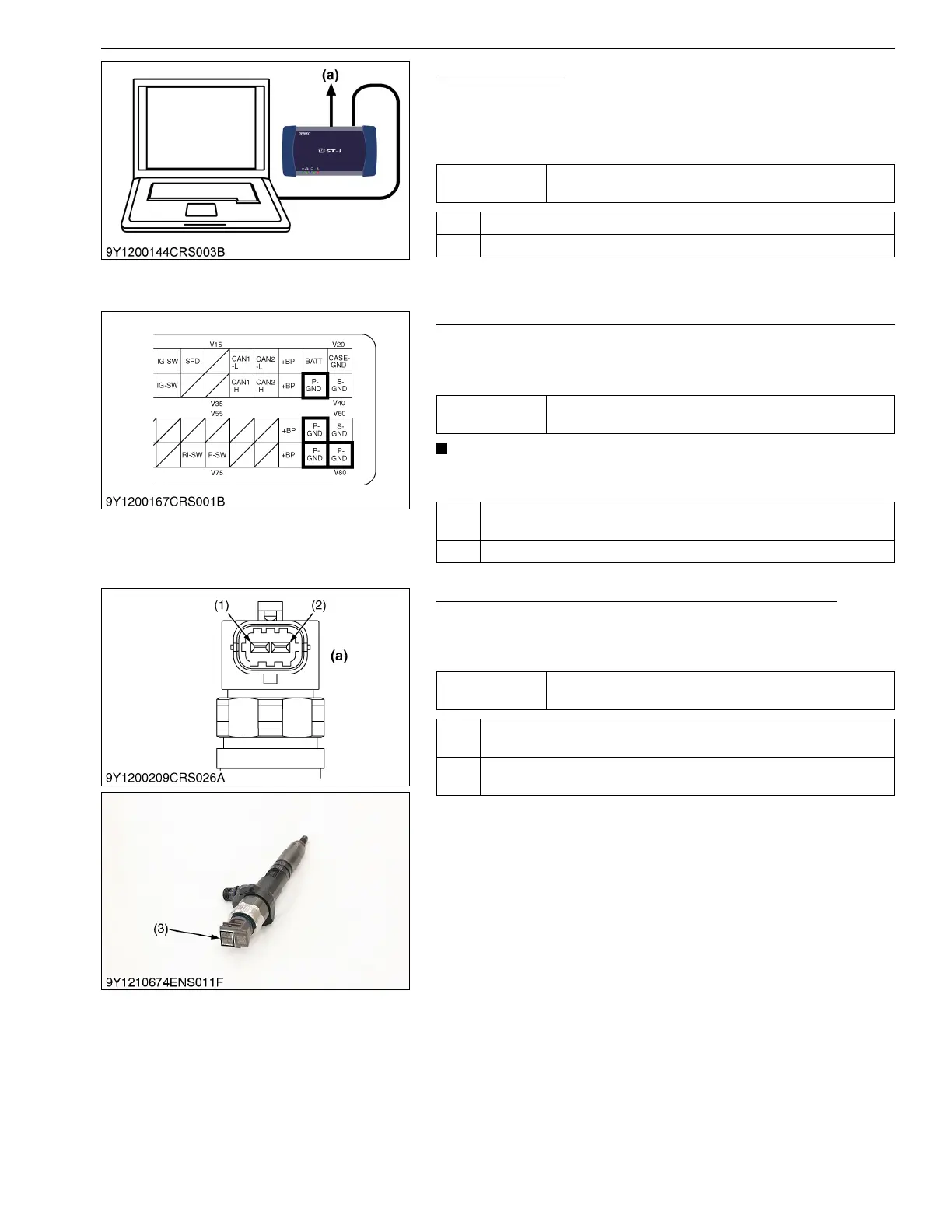
4. Measure the Resistance Between Injector Terminals
1. Unplug the injector cable connector of the cylinder indicated by
the DTC, and measure the resistance between injector
terminals (1) and (2).
9Y3200007CRS0249US0
Service
specification
No DTC is output.
OK Go to "3. Check the Connector and Wiring Harnesses for Poor Contact".
NG Faulty engine ECU → Replace.
(a) CAN1 Connector
Service
specification
Must be free from faulty connection, deformation, poor
contact or other defects.
OK Check the wiring harness and connector of P- GND terminal (Engine
ECU terminals V39, V59, V79 and V80). → Replace.
NG Check the injector wiring harnesses and connectors. → Replace.
Service
specification
0.35 to 0.55 Ω
OK Check the wiring harnesses and connectors for a poor contact. →
Repair.
NG Faulty injector → Replace (Using the diagnosis tool, write the ID (QR)
code of replaced injector in the engine ECU.)
(1) Terminal COMMON
(2) Terminal TWV
(3) ID Code
(a) Injector