COMMON RAIL SYSTEM
07-CR-E5,07-CR-TE5,07-CR-TIE5, DM
1-S188
9Y3200007CRS0258US0
1. Check the Boost Pressure Signals
1. Place the key switch in the OFF position, attach the diagnosis
tool to the CAN1 connector, and return the key switch to the ON
position again. Then, check the "Boost pressure" and "Boost
pressure sensor output voltage" on the diagnosis tool data
monitor.
2. Next, start the engine, change the depressed amount of the
accelerator pedal, and check the same items again.
• Reference value (service specification) has complete
linearity.
9Y3200007CRS0259US0
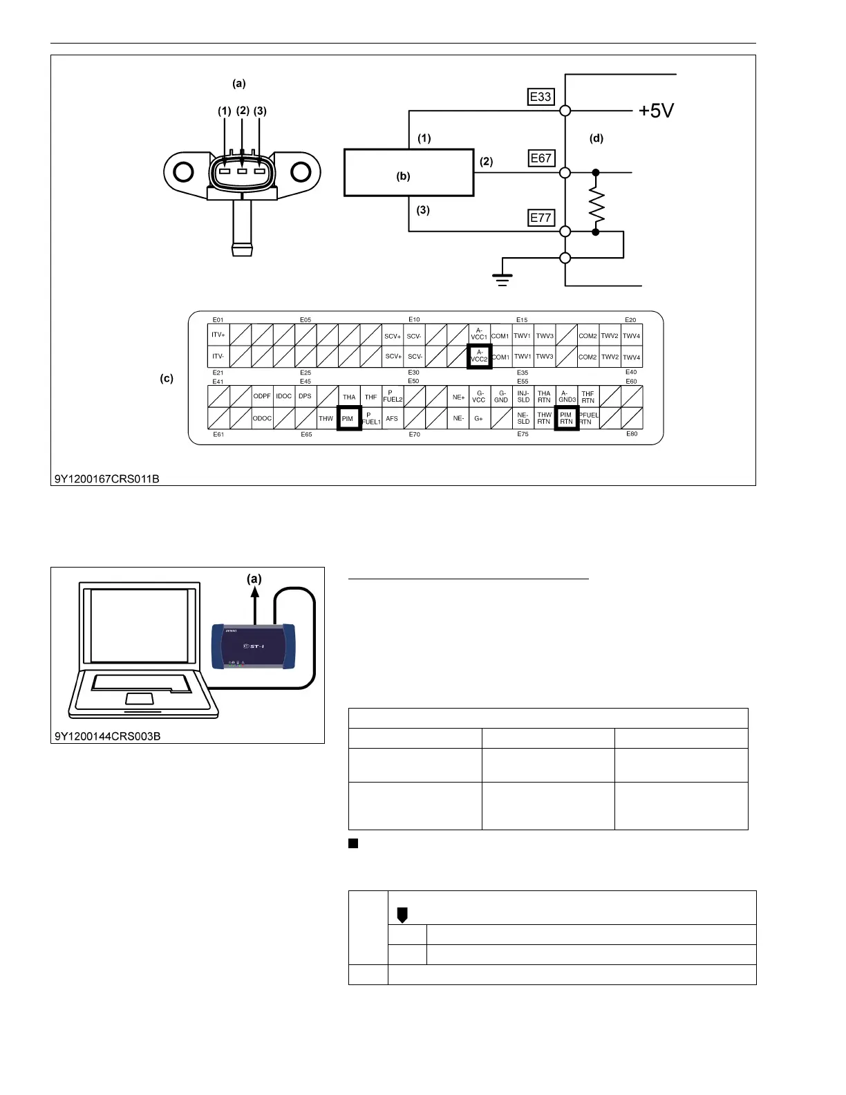
(1) Terminal A-VCC2
(2) Terminal PIM
(3) Terminal PIM RTN (a) Pin Assignment
(b) Boost Pressure Sensor
(c) Engine ECU Connector 1
(Engine Side)
(d) Engine ECU
Service specification
Engine state Actual boost pressure Output voltage
Key switch is ON
Approx. 100 kPa
(1.02 kgf/cm
2
, 14.5 psi)
Approx. 1.0 V
After engine start-up
100 to 180 kPa
(1.02 to 1.83 kgf/cm
2
,
14.5 to 26.1 psi)
1.0 to 2.2 V
OK Clear the DTC and check whether it is output again or not.
OK Normal.
NG Replace the engine ECU.
NG Go to "2. Measure the Engine ECU Terminal Voltage".
(a) CAN1 Connector