COMMON RAIL SYSTEM
07-CR-E5,07-CR-TE5,07-CR-TIE5, DM
1-S189
2. Measure the Engine ECU Terminal Voltage
1. Move the key switch from the OFF to the ON position, and
measure the voltage between engine ECU terminals E67 and
E77.
2. Next, start the engine, change the depressed amount of the
accelerator pedal, and check the same items again.
9Y3200007CRS0260US0
3. Measure the Voltage Between Boost Pressure Sensor
Terminals
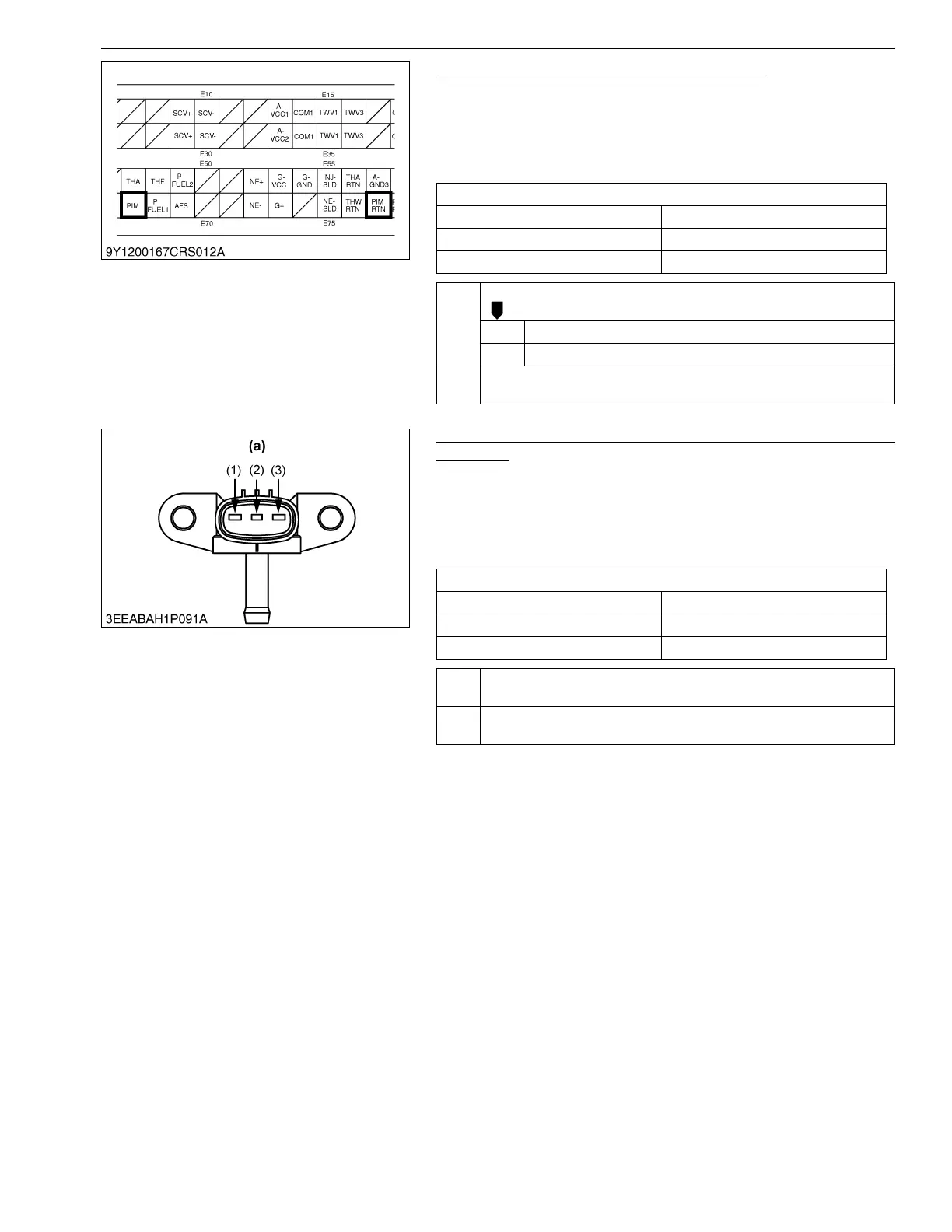
1. Place the key switch in the ON position, and measure the
voltage between terminals (2) and (3) of the boost pressure
sensor at the wiring harness side.
2. Next, start the engine, change the depressed amount of the
accelerator pedal, and check the same items again.
9Y3200007CRS0261US0
Service specification
Engine state Output voltage
Key switch ON Approx. 1.0 V
After engine start-up 1.0 to 2.2 V
OK Check the harness connectors and engine ECU pins.
OK Faulty engine ECU → Replace.
NG Replace the wiring harness, or replace the engine ECU.
NG Go to "3. Measure the Voltage Between Boost Pressure Sensor
Terminals".
Service specification
Engine state Output voltage
Key switch ON Approx. 1.0 V
After engine start-up 1.0 to 2.2 V
OK Check the wiring harness (between engine ECU terminal E67 and
sensor terminal (2)). → Replace the faulty area.
NG Go to "4. Measure the Voltage Between Boost Pressure Sensor
Terminals".
(1) Terminal A-VCC2
(2) Terminal PIM
(3) Terminal PIM RTN
(a) Pin Assignment
 Loading...


