COMMON RAIL SYSTEM
07-CR-E5,07-CR-TE5,07-CR-TIE5, DM
1-S190
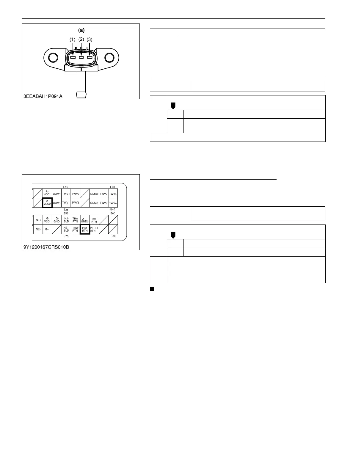
4. Measure the Voltage Between Boost Pressure Sensor
Terminals
1. Set the key switch to the OFF position, and unplug the boost
pressure sensor connector from the socket.
2. Place the key switch in the ON position, and measure the
voltage between terminals (1) and (3) of the boost pressure
sensor connector (at the wiring harness side).
9Y3200007CRS0262US0
5. Measure the Engine ECU Terminal Voltage
1. Move the key switch from the OFF to the ON position, and
measure the voltage between engine ECU terminals E33 and
E77.
• Check the hose between intake manifold and sensor, When
it is damaged, the boost pressure can not reach the sensor.
9Y3200007CRS0263US0
Service
specification
Approx. 5 V
OK Check the wiring harness connector and sensor pins.
OK Faulty boost pressure sensor → Replace.
NG 1. Replace the wiring harness.
2. Replace the boost pressure sensor.
NG Go to "5. Measure the Engine ECU Terminal Voltage".
(1) Terminal A-VCC2
(2) Terminal PIM
(3) Terminal PIM RTN
(a) Pin Assignment
Service
specification
Approx. 5 V
OK Check the harness connectors and engine ECU pins.
OK Faulty engine ECU → Replace.
NG Replace the wiring harness, or replace the engine ECU.
NG Check the wiring harness (between engine ECU terminal E33 and
sensor terminal (1) and between engine ECU terminal E77 and sensor
terminal (3)).
→ Replace the faulty area.