COMMON RAIL SYSTEM
07-CR-E5,07-CR-TE5,07-CR-TIE5, DM
1-S194
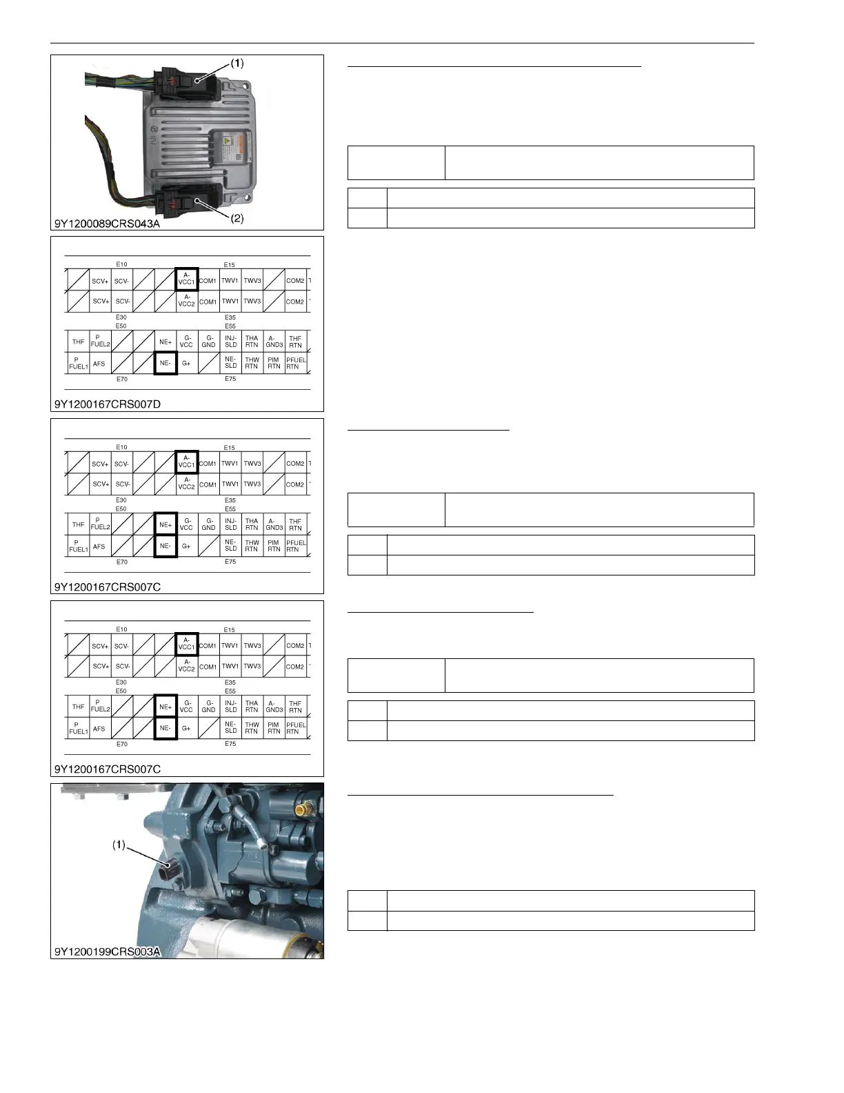
5. Measure the Engine ECU Terminal Voltage
1. Place the key switch in the OFF position, and unplug the engine
ECU wiring harness connector 1 (1) from the socket.
2. Place the key switch in the ON position, and measure the
voltage between engine ECU terminals E13 and E72.
9Y3200007CRS0271US0
6. Check the Connectors
1. Check engine ECU terminals E13, E52 and E72 (at the engine
ECU side) and the connectors (at the wiring harness side) for
incorrect connection, inappropriate fitting, poor contact.
9Y3200007CRS0272US0
7. Check the Wiring Harness
1. Check the wiring harness being connected to engine ECU
terminals E13, E52 and E72 for a short or an open circuit.
9Y3200007CRS0273US0
8. Check the Crankshaft Position Sensor
1. Disconnect the sensor and check the following items.
• Is there a large amount of magnetic foreign material
adhering to the sensor surface?
• Are there interference marks of the pulsar and the sensor?
• Are there any pulsar gear abnormalities?
9Y3200007CRS0274US0
Service
specification
Approx. 5 V
OK Go to "6. Check the connectors".
NG Replace the engine ECU.
(1) Engine ECU Wiring Harness
Connector 1 (Engine Side)
(2) Engine ECU Wiring Harness
Connector 2 (Machine Side)
Service
specification
Must be free from incorrect connection, inappropriate fitting,
poor contact.
OK Go to "7. Check the wiring harness".
NG Repair or replace.
Service
specification
Must be free from shorts and open circuit.
OK Go to "8. Check the Crankshaft Position Sensor".
NG Replace.
OK Replace the engine ECU and test.
NG Replace the sensor.
(1) Crankshaft Position Sensor
(NE Sensor)
 Loading...


