COMMON RAIL SYSTEM
07-CR-E5,07-CR-TE5,07-CR-TIE5, DM
1-S216
9Y3200007CRS0321US0
1. Check the Engine ECU Data
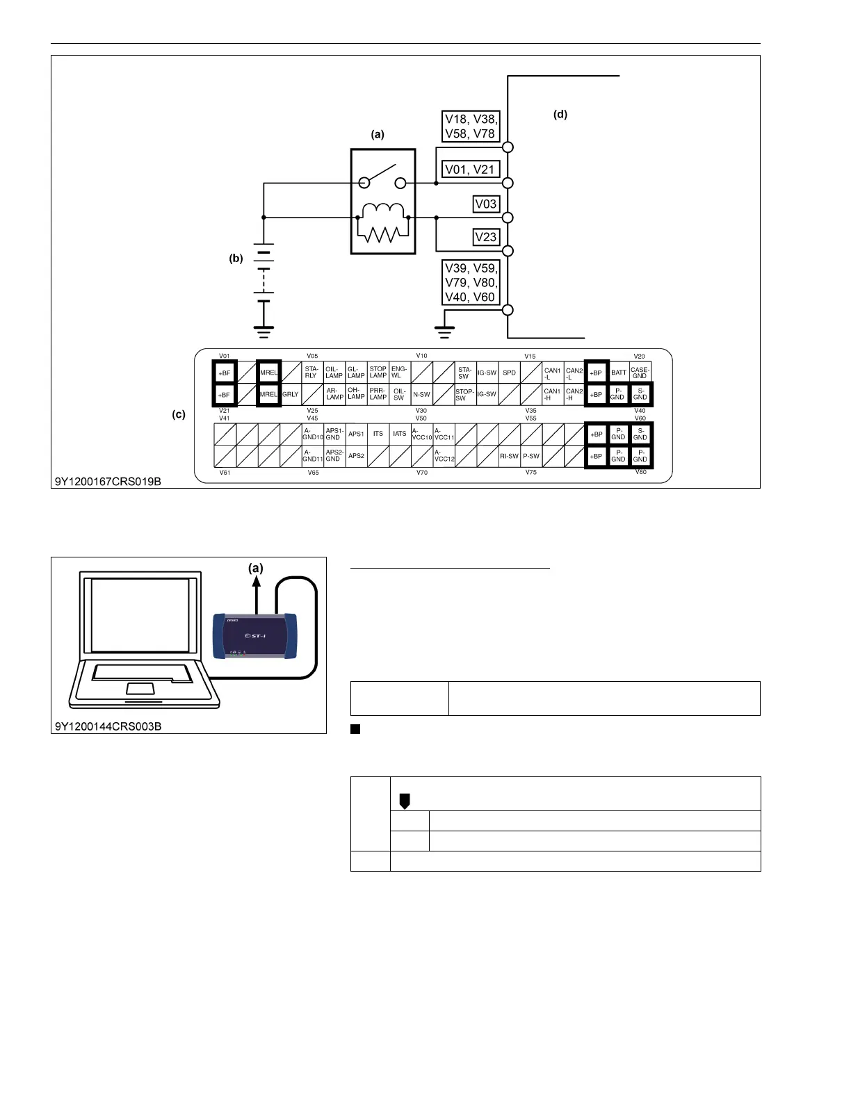
1. Place the key switch in the OFF position, attach the diagnosis
tool to the CAN1 connector, and return the key switch to the ON
position again. Then, check the "Battery voltage" status on the
data monitor.
2. Change the engine operation status, and check the "Battery
voltage".
• Try to change the engine speed as the generated voltage
changes accordingly.
9Y3200007CRS0322US0
(a) Main Relay (b) Battery (c) Engine ECU Connector 2
(Machine Side)
(d) Engine ECU
Service
specification
8 V or higher, 15 V or lower
(except intense cold temperature)
OK Clear the DTC and check whether it is output again or not.
OK Normal.
NG Replace the engine ECU.
NG Go to "2. Check the engine ECU Terminal Voltage (Part 1)".
(a) CAN1 Connector