COMMON RAIL SYSTEM
07-CR-E5,07-CR-TE5,07-CR-TIE5, DM
1-S217
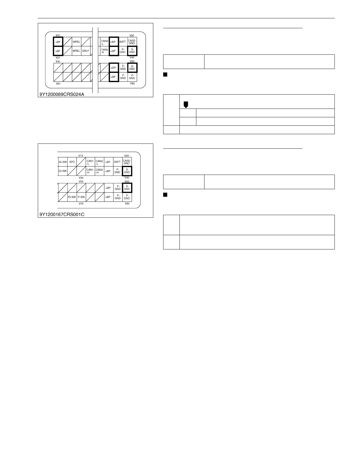
2. Check the Engine ECU Terminal Voltage (Part 1)
1. Change the engine operation status, and measure the voltage
between engine ECU terminals V18 / V38 / V58 / V78 and V40
/ V60 and between terminals V01 / V02 and V40 / V60.
• Try to change the engine speed as the generated voltage
changes accordingly.
9Y3200007CRS0323US0
3. Check the Engine ECU Terminal Voltage (Part 2)
1. Change the engine operation status, and measure the voltage
between engine ECU terminal V40 / V60 and chassis ground
terminal.
• Try to change the engine speed as the generated voltage
changes accordingly.
9Y3200007CRS0324US0
Service
specification
8 V or higher, 15 V or lower
(except intense cold temperature)
OK Check the harness connectors and engine ECU pins.
OK Faulty engine ECU → Replace.
NG Replace the wiring harness, or replace the engine ECU.
NG Go to "3. Check the Engine ECU Terminal Voltage (Part 2)".
Service
specification
Always 0.5 V or lower
OK 1. Check the charging system, the battery itself, wiring harness and
cables. → Replace the faulty area.
2. Locate the cause of excessively high or low voltage.
NG Check the wiring harness between engine ECU terminal and the body
ground terminal. → Replace the defects.