COMMON RAIL SYSTEM
07-CR-E5,07-CR-TE5,07-CR-TIE5, DM
1-S270
9Y3200007CRS0421US0
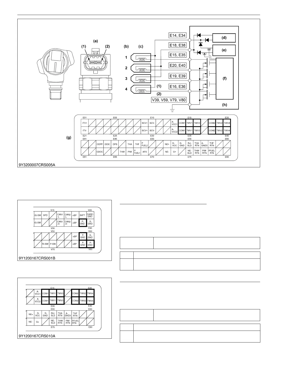
1, Check the "P- GND" Wiring Harness
1. Place the key switch in the OFF position, unplug the engine
ECU wiring harness connector 2 (machine side) from the
socket, and measure the resistance between each of engine
ECU terminals V39, V59, V79 or V80 and the chassis ground (at
the wiring harness side).
9Y3200007CRS0411US0
2. Check the Wiring Harness Connectors and Engine ECU Pins
1. Place the key switch in the OFF position, unplug the engine
ECU connector 1 (engine side) from the socket, and check the
engine ECU pins for faulty connection, deformation, poor
contact or other defects.
9Y3200007CRS0412US0
(1) Terminal COMMON
(2) Terminal TWV
(a) Pin Assignment
(b) Engine Cylinder No.
(c) Injector
(d) Rated amperage circuit
(e) High-voltage generating
circuit
(f) Control circuit
(g) Engine ECU Connector 1
(Engine Side)
(h) Engine ECU
Service
specification
1.5 Ω or lower
OK Go to "2. Check the Wiring Harness Connectors and Engine ECU Pins".
NG Check the "P- GND" wiring harness. → Replace.
Locate the cause of open circuit, or increase its resistance value.
Service
specification
Must be free from faulty connection, deformation, poor
contact or other defects.
OK Go to "3. Measure the Engine ECU Terminal Voltage (Part 1)".
NG Replace wiring harness connectors and engine ECU pins, or replace
them if defective.