COMMON RAIL SYSTEM
07-CR-E5,07-CR-TE5,07-CR-TIE5, DM
1-S271
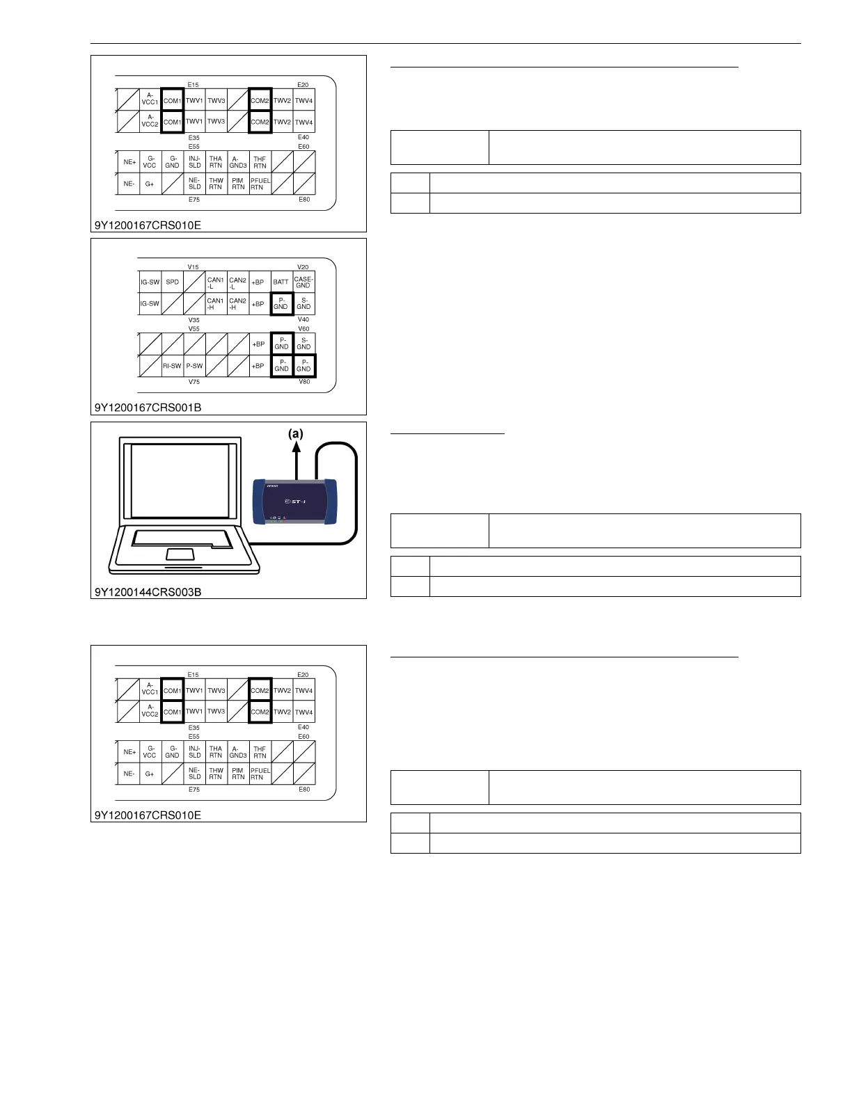
3. Measure the Engine ECU Terminal Voltage (Part 1)
1. Place the key switch in the ON position, and measure the
voltage between engine ECU terminal E14 / E34 or E18 / E38
and "P- GND" terminal.
9Y3200007CRS0413US0
4. Check the DTC
1. Place the key switch in the OFF position, and attach the
diagnosis tool to the CAN1 connector.
2. Start the engine, and clear the past DTCs.
3. Read the DTC again.
9Y3200007CRS0414US0
5. Measure the Engine ECU Terminal Voltage (Part 2)
1. Place the key switch in the OFF position, unplug the engine
ECU wiring harness connector 1 (engine side) from the socket,
return the key switch to the ON position again, and measure the
voltage between each of engine ECU terminal pins E14 / E34
and E18 / E38 and the "P -GND" terminal (at the wiring harness
side).
9Y3200007CRS0415US0
Service
specification
Approx. 6 V
OK Go to "4. Check the DTC".
NG Go to "5. Measure the Engine ECU Terminal Voltage (Part 2)".
Service
specification
Normal (No DTC is output.)
OK Normal.
NG Faulty engine ECU → Replace.
(a) CAN1 Connector
Service
specification
Approx. 6 V
OK Go to "6. Check the Wiring Harness".
NG Faulty engine ECU → Replace.
 Loading...


