COMMON RAIL SYSTEM
07-CR-E5,07-CR-TE5,07-CR-TIE5, DM
1-S283
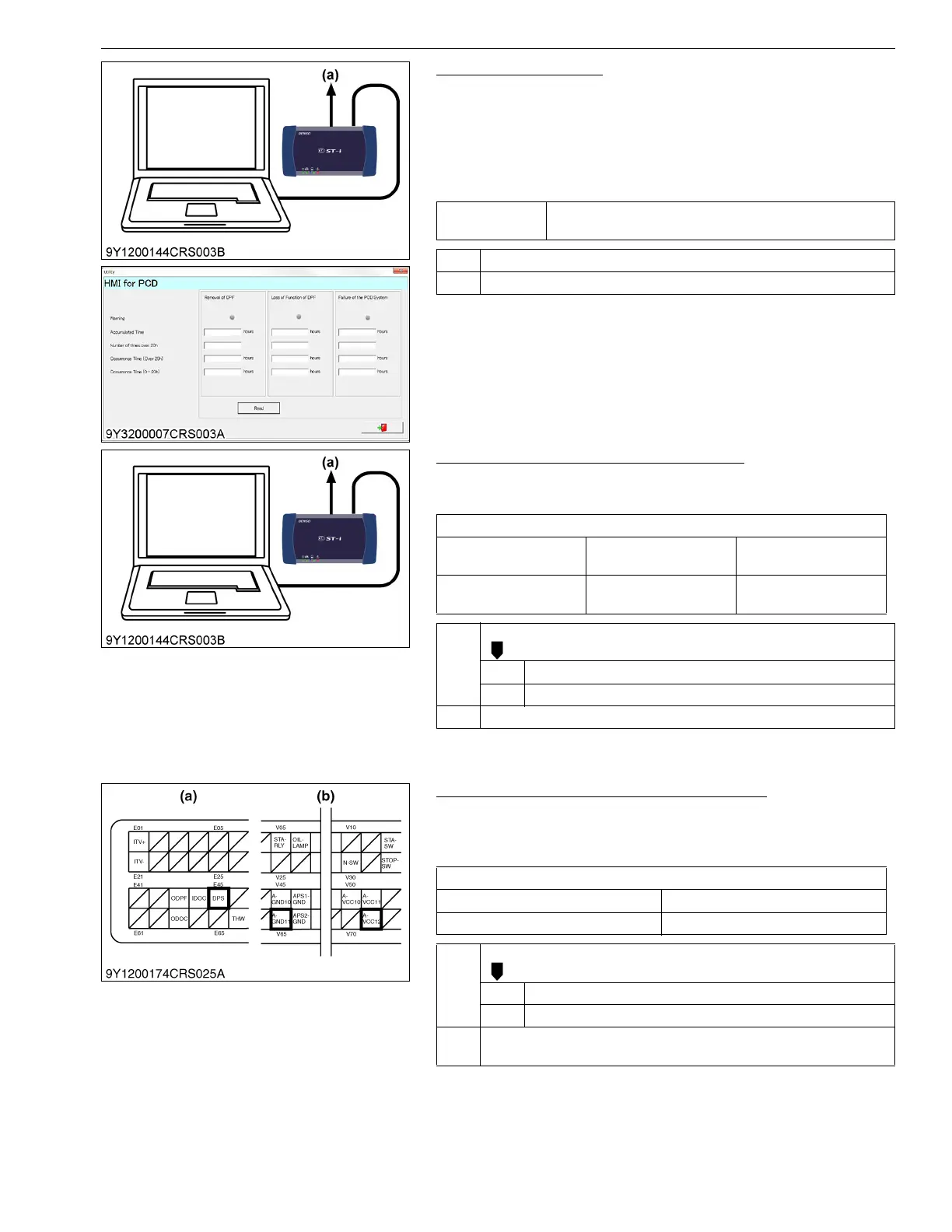
1. Check the Warnings
1. Place the key switch in the OFF position, attach the diagnosis
tool to the CAN1 connector, and return the key switch to the ON
position again.
2. Check the "HMI for PCD" screen and confirm that which
warnings are displayed.
3. Check whether the device is under tampering.
9Y3200007CRS0566US0
2. Check the Differential Pressure Signals
1. Check the "Differential pressure" and "Differential pressure
sensor output voltage" on the diagnosis tool data monitor.
9Y3200007CRS0438US0
3. Measure the Engine ECU Terminal Voltage
1. Move the key switch from the OFF to the ON position, and
measure the voltage between engine ECU terminals E45 and
V71.
9Y3200007CRS0439US0
Service
specification
No warnings are displayed
OK Normal
NG Go to "2. Check the Differential Pressure Signals".
(a) CAN1 Connector
Service specification
Engine state
Actual differential
pressure
Output voltage
Key switch is ON
Approx. 0 Pa
(0 kgf/cm
2
, 0 psi)
Approx. 0.7 V
OK Clear the DTC and check whether it is output again or not.
OK Normal.
NG Replace the engine ECU.
NG Go to "3. Measure the Engine ECU Terminal Voltage".
(a) CAN1 Connector
Service specification
Engine state Output voltage
Key switch ON Approx. 0.7 V
OK Check the harness connectors and engine ECU pins.
OK Faulty engine ECU → Replace.
NG Replace the wiring harness, or replace the engine ECU.
NG Go to "4. Measure the Voltage Between Differential Pressure Sensor
Terminals".
(a) Engine ECU Connector 1
(Engine Side)
(b) Engine ECU Connector 2
(Machine Side)