COMMON RAIL SYSTEM
07-CR-E5,07-CR-TE5,07-CR-TIE5, DM
1-S319
9Y3200007CRS0512US0
1. DTC Judgment
1. Place the key switch in the OFF position, and attach the
diagnosis tool to the CAN1 connector.
2. Place the key switch in the ON position, check whether the DTC
is output or not.
• If the "CAN 2 Bus off error" is output at the same time, carry
out this inspection first.
• Make sure that the engine ECU on the machine side
operates properly.
9Y3200007CRS0513US0
2. Check the Wiring Related to the CAN of the Common Rail
System
1. Check the wiring harness and connectors being connected to
engine ECU terminals V17 and V37 for a short or an open
circuit.
• Refer to "6.[3] ELECTRIC SYSTEM INSPECTION
PROCEDURE - (1) Basics of Checking Electrical /
Electronic Circuit Systems". (Refer to page 1-S326)
9Y3200007CRS0514US0
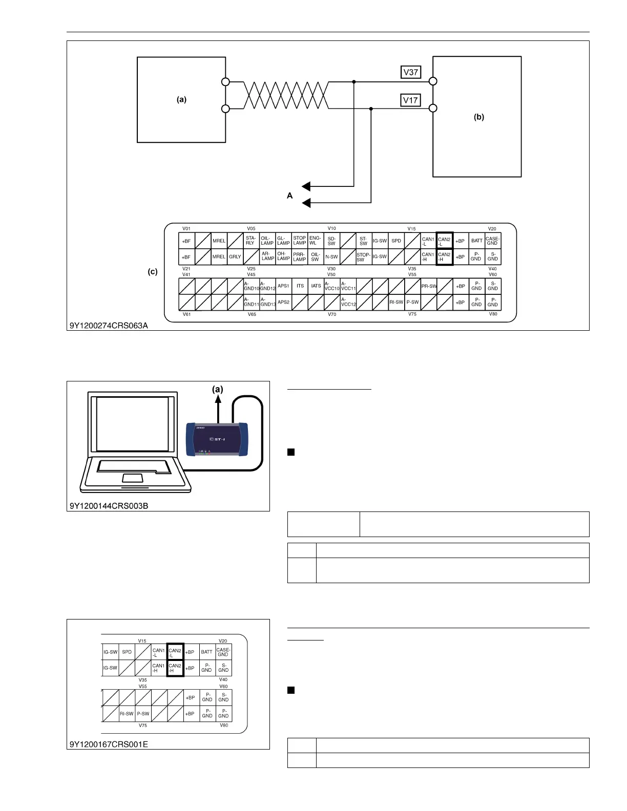
(a) Machine ECU (b) Engine ECU (c) Engine ECU Connector 2
(Machine Side)
A: To Other ECU
Service
specification
DTC must not be output.
OK Normal.
NG Go to "2. Check the Wiring Related to the CAN of the Common Rail
System".
(a) CAN1 Connector
OK Replace the engine ECU.
NG Replace the faulty areas.
 Loading...


