COMMON RAIL SYSTEM
07-CR-E5,07-CR-TE5,07-CR-TIE5, DM
1-S331
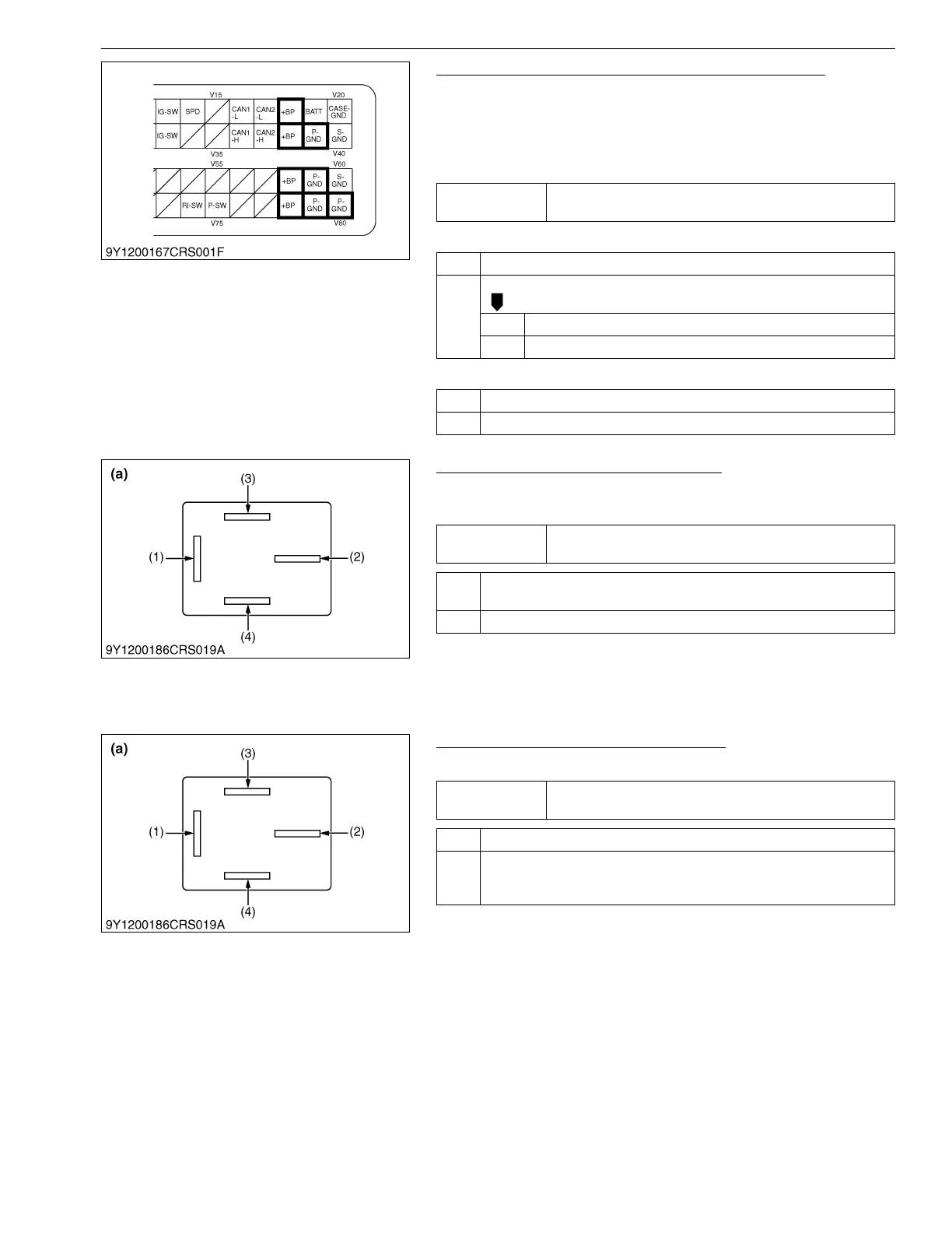
1. Measure the Engine ECU +BP and Ground Voltage
1. Turn the key switch ON and measure the voltage between the
engine ECU +BP terminals (V18 / V38 / V58 / V78) and ground
(body / battery terminal). Then measure voltage between the
engine ECU ground terminals (V40 / V60) and ground (body /
battery terminal).
+BP terminal unsatisfactory
Ground terminal unsatisfactory
9Y3200007CRS0534US0
2. Check the Relay Terminal Voltage -1
1. Turn the key switch ON and measure voltage at relay terminal
2 (2).
9Y3200007CRS0535US0
3. Check the Relay Terminal Voltage - 2
1. Measure voltage at relay terminal 1 (1).
9Y3200007CRS0536US0
Service
specification
+BP terminal - Ground; greater than or equal to 10 V
P-GND terminal - Ground; Less than or equal to 0.5 V
OK Normal.
NG Check battery, wiring harness, ground wire.
OK Go to "2. Check the Relay Terminal Voltage -1".
NG Replace.
OK Normal.
NG Check engine ECU wiring harness ground.
Service
specification
10 V or higher
OK Check wiring between relay and engine ECU. → Replace.
Check for connector connection fault. → Repair or replace.
NG Go to "3. Check the Relay Terminal Voltage - 2".
(1) Terminal 1
(2) Terminal 2
(3) Terminal 3
(4) Terminal 4
(a) Main Relay Pin Assignment
Service
specification
10 V or higher
OK Go to "4. Check the Relay Terminal Voltage - 3".
NG Check for a wiring harness open circuit and / or connector connection
fault. → Repair or replace.
Inspect fuse. → Replace.
(1) Terminal 1
(2) Terminal 2
(3) Terminal 3
(4) Terminal 4
(a) Main Relay Pin Assignment