COMMON RAIL SYSTEM
07-CR-E5,07-CR-TE5,07-CR-TIE5, DM
1-S332
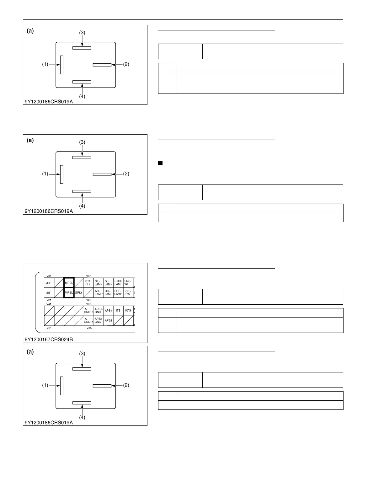
4. Check the Relay Terminal Voltage - 3
1. Measure voltage at relay terminal 3 (3).
9Y3200007CRS0537US0
5. Check the Relay Terminal Voltage - 4
1. Turn the key switch OFF and measure voltage at relay terminal
4 (4).
• Perform measurement two seconds after cycling the key
switch ON → OFF.
9Y3200007CRS0538US0
6. Check the Relay Terminal Voltage - 5
1. With the key switch OFF, measure voltage at the engine ECU
main relay terminals (V03 / V23).
9Y3200007CRS0539US0
7. Check the Relay Terminal Voltage - 6
1. Turn the key switch ON and measure voltage at relay terminal
4 (4).
9Y3200007CRS0540US0
Service
specification
10 V or higher
OK Go to "5. Check the Relay Terminal Voltage - 4".
NG Check for a wiring harness open circuit and / or connector connection
fault. → Repair or replace.
Inspect fuse. → Replace.
(1) Terminal 1
(2) Terminal 2
(3) Terminal 3
(4) Terminal 4
(a) Main Relay Pin Assignment
Service
specification
10 V or higher
OK Go to "6. Check the Relay Terminal Voltage - 5".
NG Check the relay. → Replace.
(1) Terminal 1
(2) Terminal 2
(3) Terminal 3
(4) Terminal 4
(a) Main Relay Pin Assignment
Service
specification
10 V or higher
OK Go to "7. Check the Relay Terminal Voltage - 6".
NG Check wiring harness between relay and engine ECU and connectors. →
Replace.
Service
specification
Approx. 0 V
OK Faulty relay contacts → Replace.
NG Go to "8. Check the Key Switch Signal -1".
(1) Terminal 1
(2) Terminal 2
(3) Terminal 3
(4) Terminal 4
(a) Main Relay Pin Assignment