COMMON RAIL SYSTEM
07-CR-E5,07-CR-TE5,07-CR-TIE5, DM
1-S333
8. Check the Key Switch Signal -1
1. Connect the diagnosis tool to diagnostic connector (CAN1
connector) and turn the key switch ON.
2. Using the diagnosis tool data monitor function, verify the "Key
Switch" data when the key switch is turned ON then OFF.
• Do not keep the key switch in the OFF position for more
than 2 seconds, otherwise a communication error will
occur.
9Y3200007CRS0541US0
9. Check the Key Switch Signal -2
1. Place the key switch in the ON position, and measure the
voltage at engine ECU terminal V13 / V33.
9Y3200007CRS0542US0
10. Check the Key Switch -1
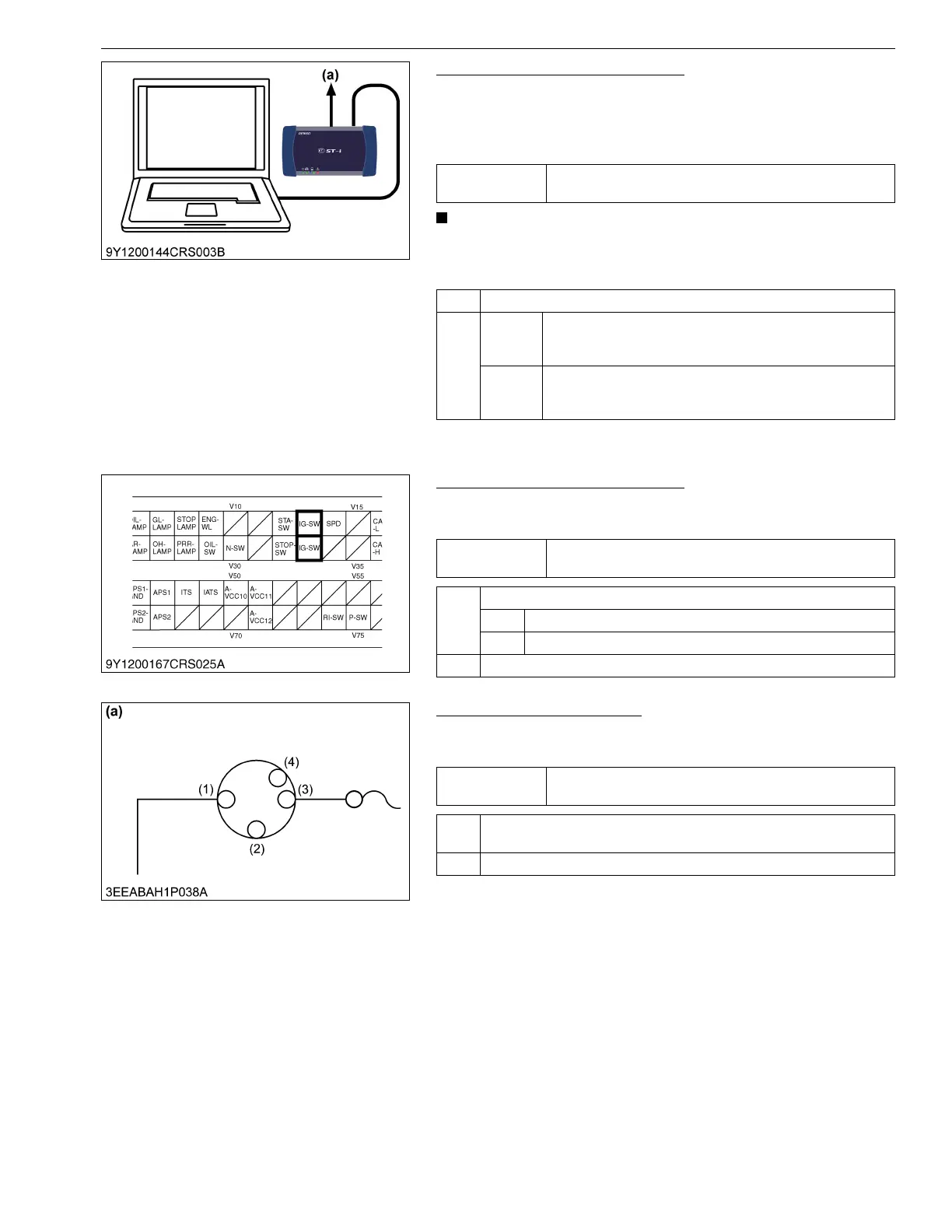
1. Set the key switch to the ON position, and measure the voltage
at the key switch output terminal (3).
9Y3200007CRS0543US0
Service
specification
When the key switch is set to the ON and OFF, the data
output is turned ON and OFF respectively.
OK Engine ECU internal fault → Replace the engine ECU.
NG Con-
stantly
ON
Engine ECU internal fault → Replace the engine ECU.
Consis-
tently
OFF
Go to "9. Check the Key Switch Signal -2".
(a) CAN1 Connector
Service
specification
10 V or higher
OK Check whether the connector is poorly connected.
OK Replace the engine ECU.
NG Repair the connector.
NG Go to "10. Check the Key Switch -1".
Service
specification
10 V or higher
OK Check the wiring harness between the key switch output terminal and
engine ECU terminal (V13 / V33), and the fuse. → Replace.
NG Go to "11. Check the Key Switch - 2".
(1) Input Terminal
(2) ACC
(3) Output Terminal
(4) START
(a) Key Switch