COMMON RAIL SYSTEM
07-CR-E5,07-CR-TE5,07-CR-TIE5, DM
1-S55
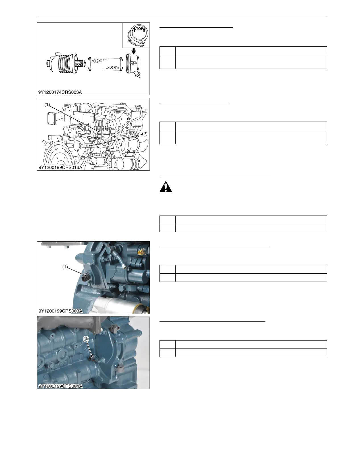
3. Check the Intake System
1. Check in accordance with "6.[1] AIR INTAKE SYSTEM
INSPECTION PROCEDURE". (Refer to page 1-S320)
9Y3200007CRS0085US0
4. Check the Fuel System
1. Check in accordance with "6.[2] FUEL SYSTEM INSPECTION
PROCEDURE". (Refer to page 1-S321)
9Y3200007CRS0086US0
5. Check the Accelerator Position Sensor
• When checking, pay attention to the angle of mounting
instead of the output signal quality.
1. Inspect in accordance with the operator's manual.
9Y3200007CRS0087US0
6. Check the Crankshaft Position Sensor
1. Refer to DTC P0335 and P0336, and implement checking of the
crankshaft position sensor.
9Y3200007CRS0039US0
7. Check the Camshaft Position Sensor
1. Refer to DTC P0340 and P0341, and implement checking of the
camshaft position sensor.
9Y3200007CRS0088US0
OK Go to "4. Check the Fuel System".
NG Repair in accordance with "6.[1] AIR INTAKE SYSTEM INSPECTION
PROCEDURE". (Refer to page 1-S320)
OK Go to "5. Check the Accelerator Position Sensor.
NG Repair in accordance with "6.[2] FUEL SYSTEM INSPECTION
PROCEDURE". (Refer to page 1-S321)
(1) Rail (2) Supply Pump
OK Go to "6. Check the Crankshaft Position Sensor".
NG Replacement of accelerator position sensor.
OK Go to "7. Check the Camshaft Position Sensor".
NG Replace the crankshaft position sensor-related parts.
(1) Crankshaft Position Sensor
(NE Sensor)
OK Go to "8. Check the EGR Valve".
NG Replace the camshaft position sensor-related parts.
(1) Camshaft Position Sensor
(G Sensor)