COMMON RAIL SYSTEM
07-CR-E5,07-CR-TE5,07-CR-TIE5, DM
1-S56
8. Check the EGR Valve
Refer to "5.[2] DIAGNOSTIC PROCEDURE BY DTC" for the
detailed EGR-related check. A simplified version is shown below.
(Refer to page 1-S133)
• Check that the EGR valve does not open before the engine
has warmed up [coolant temperature: 50 °C (122 °F)].
1. Use the monitor function to check whether the actual opening
meets the target opening.
2. Perform an active test (EGR actuation test).
9Y3200007CRS0089US0
9. Check the Data Related to Pressure Control
1. Measure the "Target rail pressure" and "Actual rail pressure"
when accelerator is operated as indicated below using the
diagnosis tool data monitor function.
9Y3200007CRS0090US0
Service
specification
Refer to "1.[5].(2) Normal Value". (Refer to page 1-M16)
In addition, for the check procedures refer to
"5.[2] DIAGNOSTIC PROCEDURE BY DTC". (Refer to page
1-S133)
Service
specification
(Low side)
When target EGR valve openings of 0 % and 15 % are given
alternately, there must not be disparity in the actual EGR
valve opening.
(High side)
When target EGR valve openings of 35 % and 60 % are
given alternately, there must not be disparity in the actual
EGR valve opening.
OK Go to "9. Check the Rail Pressure Sensor and Supply Pump".
NG Replace the EGR valve.
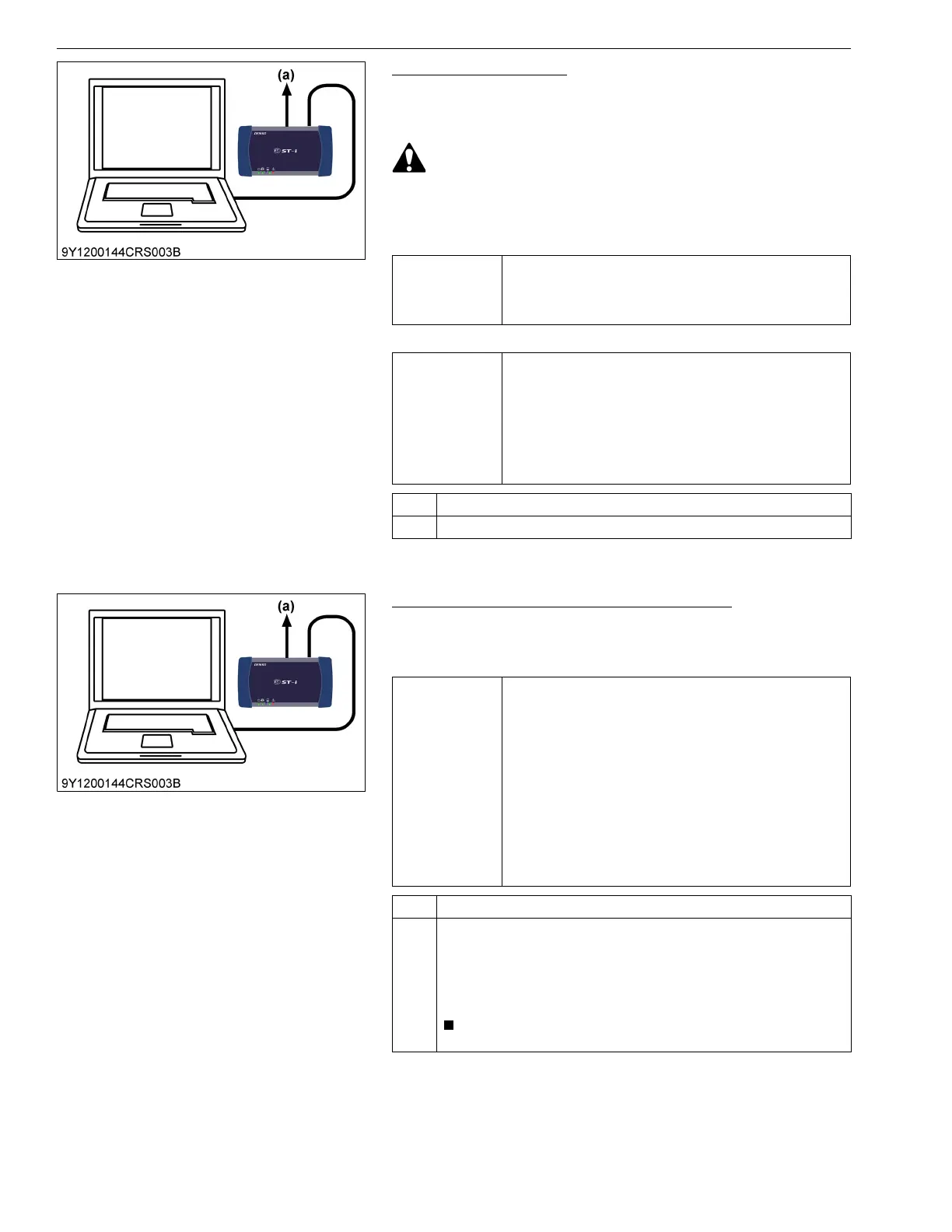
(a) CAN1 Connector
Service
specification
The "Actual rail pressure" always follow to the "Target rail
pressure".
1. When idling:
40 to 50 MPa (410 to 500 kgf/cm
2
, 5800 to 7200 psi)
2. Accelerator opening
0 → 100 % (During acceleration):
Maximum value 95.0 to 130 MPa (969 to 1320 kgf/cm
2
,
13800 to 18800 psi)
3. No-load maximum speed:
95.0 to 115 MPa (969 to 1170 kgf/cm
2
, 13800 to
16600 psi)
4. The numerical value is stable under normal operating and
the target value corresponds with actual pressure value.
OK Go to "10. Check the Injector (Including the Pipes, etc.)".
NG (Check the trouble related to pressure
Refer to the pressure system items (P0087, P0088, P0089 and P0093
(Refer to page 1-S140)) and SCV abnormality items (P0628 and P0629
(Refer to 1-S223)) in "5.[2] DIAGNOSTIC PROCEDURE BY DTC",
perform diagnosis for the engine ECU, wiring harness and sensor, and
replace the required parts.
• Some diagnosis items above may be mentioned twice.
(a) CAN1 Connector