KurzB‐SeriesOperationsGuide6–6
Flow Meter Configuration
Setting Up the Flow Controller
A4‐20mAoutputcanbeusedasapositioncommandsignalforacontrolvalveormotordrive
RPM.TousetheB‐Seriesasanautomaticflowcontroller,connectoneofits4‐20mAoutputsto
thecontrolvalve,damper,ormotorcontroller.Itwillregulatethe
flowbasedonafixedflowset
pointvalueorananaloginputforthesetpoint.
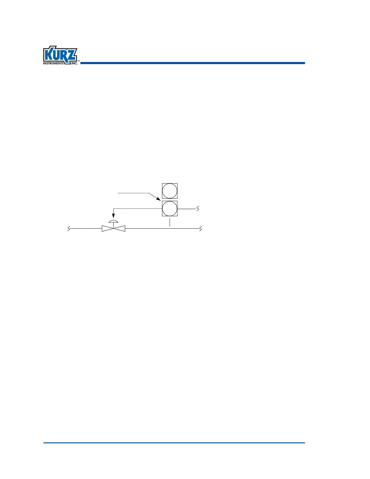
ThefollowingexamplehastheB‐Seriesflowmeteractuatingavalvebasedonanexternalset
pointoftheflowrate.Thesecond4‐20mAoutputchannelissendingtheflowrate
signal
elsewhere,althoughtemperaturecanbespecifiedinsteadofflowrate.PIDcontroloftheprocess
ismanuallyconfigured.Thecontroloutputcanbecontrolledmanuallyfromthedisplaytoverify
therangeoperationofthecontrollooportomanuallysettheoutput(controlvalve)atafixed
position.
Setting Up A PID
TosetupaPID:
1> Mechanicallymountallcomponents,testforleaks,andcheckflowcontrolactuatormotion
ormotorcontrolleraction.
2> Electricallyconnectallcomponents.Wire‐inoneofthe4‐20mAoutputs.Thedefault
outputoftheflowmeterisforlooppowered4‐20mA.Refertothedevicewiringdiagram
if youneedittobeself‐powered.
3> Configurethe4‐20mAoutputscaleforthecontroldeviceusingvelocityorflowrateunits
todeterminetheprocessflowunitsatthe4mAoutputpositionandthe20mAoutput
position.
4> Configurethesetpointsourceforthe:
— Externalanaloginputbyconfiguringthe4‐20mAscaleusingappropriate
engineeringunits.
— InternalsetpointusingaflowrateorvelocityvaluethatwillmaintainthePID
controlvariable(flowrateorvelocity)atafixedvalue.Thissetpointcanbechanged
atthemeterkeypadorusingaModbuscommand.
5> Tunethecontrolloopforstableoperationoverthespecifiedflowrange.
 Loading...