KurzB‐SeriesOperationsGuide6–8
Flow Meter Configuration
Forexample,theSeries454PFTBmodelisdesignedtodirectlydriveasolenoid(upto12Wat24
VDC)toprovidethecompressedgascleaningtothesensor.FortheK‐BAR2000PB,onlyoneofthe
sensorcontrolboardsneedstohavethesolenoiddrivemodifications.Allunitsrespond
tothe
externaltriggercommandatthesametimeandmaskthepurgeblastfromtheoutputdata.
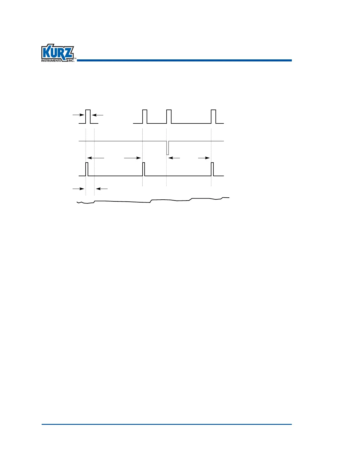
Figure 6‐1. Maskedpurgeblast
Wiring for the Purge Controller
Thepurgecontrollersetuprequiresconnectinga24VDC12WmaximumsolenoidtotheDO2or
solidstaterelaychannel#2.Pin#TB6‐1is+24VDCandTB6‐2istheGNDconnection.Seethefield
wiringdiagramforanexampleofthesolenoidwiring.Therecommendedwiring
gageis18 AWG
(1.02mm),althoughthegageandlengtharenotcriticalforthisconnection.
Note ThiswiringinformationonlyappliestothePurgeversionofthe
Series 454PFTB.
ThecontactclosureforactivatingthepurgeisonpinsTB6‐8ordigitalinput1(DI1)andground
(TB6‐6).Thewidthoftheactivationpulsemustbeatleast25 mslong,andthepurgewillstarton
theleadingedge(orfallingfromlogichightolow).
Purge
Output
Purge Start
Contact
Closure
Internal
Purge Timer
Flow Data
Output
Purge Time
Hold Time
Interval Interval
 Loading...