218 Lifting Arms
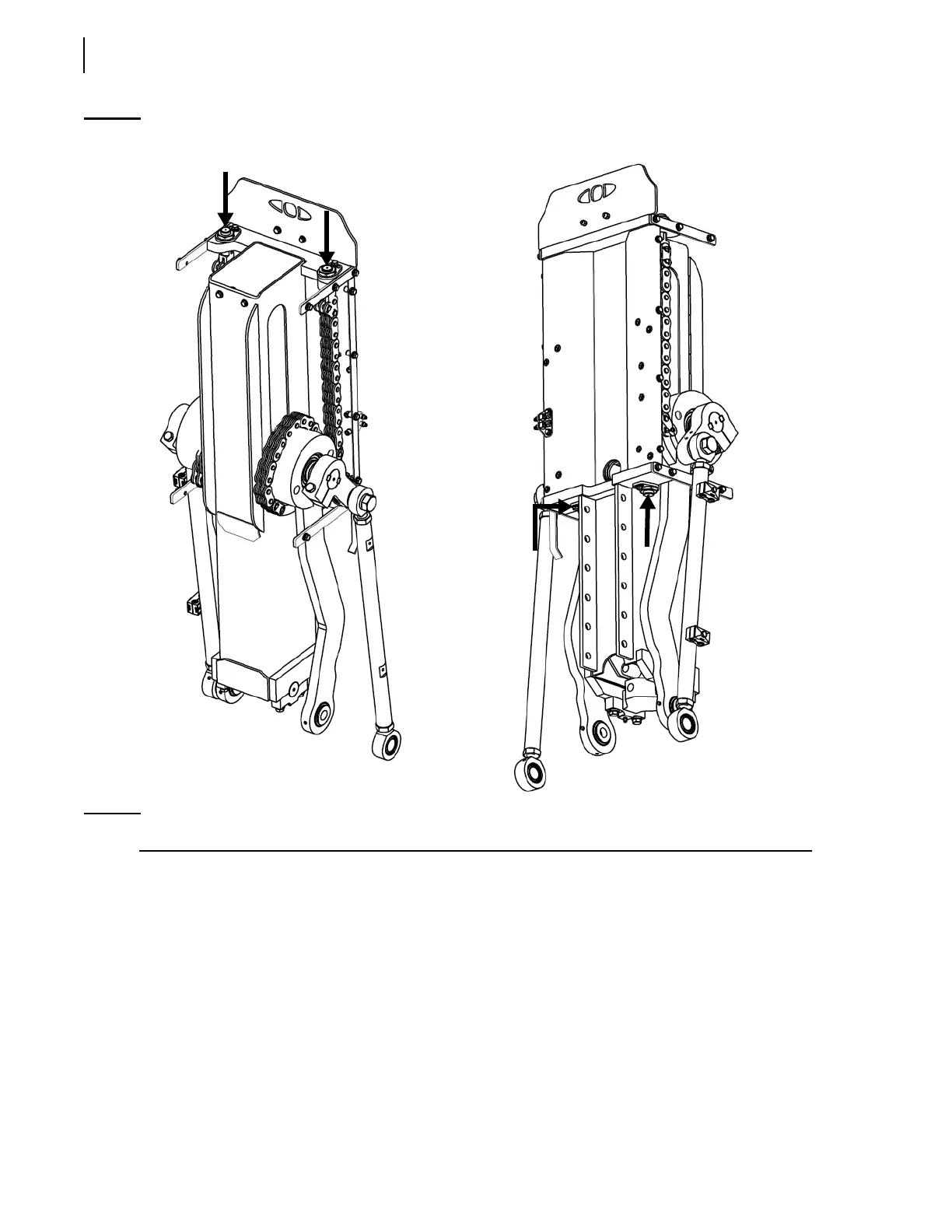
Figure 10-12
Arm alignment (the location of the chain tension bolts is indicated by arrows)
NOTE: The above illustration shows a standard Right-Hand
TM
arm.
Bleeding Air Out of the Lifting Arm Hydraulic
Circuit
When replacing a hydraulic cylinder, a holding valve, or when opening the Right Hand™ hydraulic
circuit, air may enter the hoses located between the proportional valve and the arm cylinder. Because
air cannot be completely removed by the normal use of the arm, the system must be bled.
The Right Hand™ arm is composed of three hydraulic subcircuits, which must be bled individually
depending on the modifications done. Those subcircuits are the following: