MX-FR Series Modular Matrix Frames – User's Manual 51
5
Software Control - The Built-in Web
The MX-CPU2 board has a feature which allows to connect and control the
as in the case of Lightware Device Controller, but numerous information is
displayed and many settings are available.
ç
ç
ç
System Requirements
Supported Operating Systems:
Supported Web Browsers: Mozilla Firefox, Google Chrome, Apple Safari.
Establishing the Connection
ATTENTION!
port, be sure that the computer is in the same network as the router.
If the computer has multiple Ethernet connections (e.g. wired and
wireless) you will have to know the IP address for the one that is
used for controlling the matrix.
Step 1. Connect the matrix and the computer either via
▪ Ethernet, with LAN patch cable (to a hub, switch or router), or
▪ Ethernet, with LAN cross cable (directly to a computer).
Step 2. Change to the desired IP settings if it is needed.
Step 3. Type the IP address to the address bar of the web browser and
press enter (factory default address is 192.168.254.254).
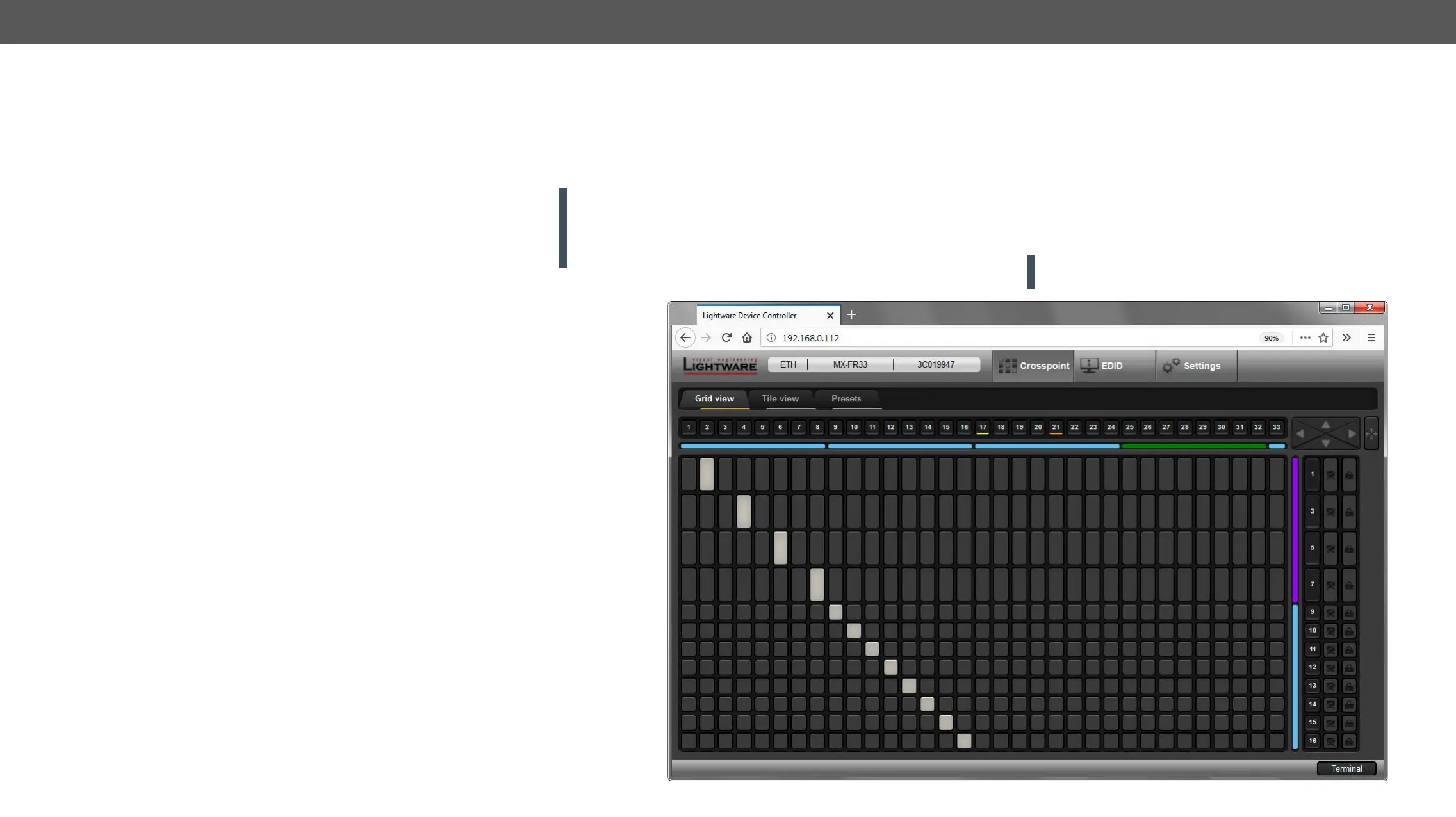
The Layout of the Built-in Web
The built-in web page allows almost the same controlling functions
which are available via the Lightware Device Controller.
ATTENTION! Only one web page is allowed to open simultaneously
.