4. Operation MX-FR Series Modular Matrix Frames – User's Manual 41
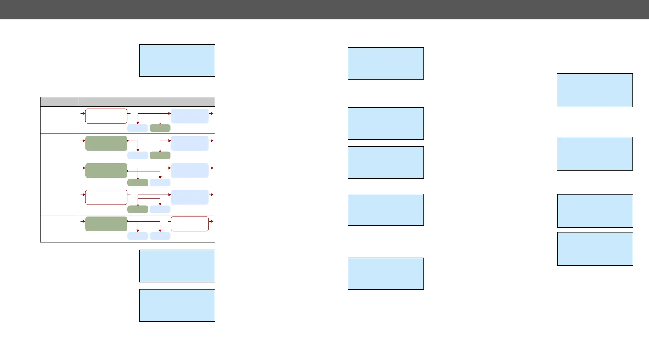
The Add-on source setting is accessible only with MXD-UMX-IB. The
functions can be set here. Two signal
conversions are shown. S represents
An represents the
analog stereo port and D represents
the digital audio which is embedded
in the HDMI signal on the video port. Possible options are shown
below:
The Analog audio Input submenu
contains settings like volume, balance,
etc. for the analog stereo audio port
Available only at MXD-UMX-IB.
The Analog audio Output submenu
contains settings like volume, balance,
etc. for the analog stereo audio port
Available only at MXD-UMX-IB.
Input 2 settings
~Add-On Source ~
~ An->D;An->S ~
Analog Audio Input
Input 2 settings
Add-On Source
An->D;An->S
~Analog Audio Inpu>>
AnalogS/PDIF
An->D;An->S
HDMI deembedded
from input port
HDMI embedded
to crosspoint
x
AnalogS/PDIF
An->D;D->S
HDMI deembedded
from input port
HDMI embedded
to crosspoint
AnalogS/PDIF
D->An;S->D
HDMI deembedded
from input port
HDMI embedded
to crosspoint
AnalogS/PDIF
S->D;S->An
HDMI deembedded
from input port
HDMI embedded
to crosspoint
x
AnalogS/PDIF
D->S;D->An
HDMI deembedded
from input port
HDMI embedded
to crosspoint
x
LCD legend Connections
Input 2 settings
An->D;An->S
Analog Audio Input
~Analog Audio Outp>>
Supported Boards: MX-DVIDL-IB
The input cable equalization can be
set to 3, 9, 25, 35, 40 dB, or Auto. Use the
left ◄ and right ► buttons to change
the value.
Supported Boards: MX-3GSDI-IB
Use the up ▲ and down ▼ buttons to
select the parameter to be changed.
Use the left ◄ and right ► buttons to
change the value.
The Equalization can be set to Auto
(recommended) or 0 dB. The later
setting disables equalization.
The Audio source selects the audio
signal that is embedded in the
forwarded HDMI stream: it can be set
to SDI, S/PDIF or No audio.
The Video mode sets the signal type to
DVI or HDMI mode which is sent
towards the matrix crosspoint. The
Audio dependent mode sends HDMI
signal to the crosspoint if the audio
source is set to embed audio from SDI
Frame compatible mode sets the signal type according to
the output board types in the matrix frame If there are only HDMI
compatible output boards then the signal type will be HDMI.
The incoming SDI embedded audio
channels can be rearranged and
allocated to HDMI audio channels.
The channel allocation preset can be
selected with the Aud.Preset setting.
SDI audio allocation presets are
common for all SDI input ports in the matrix.
Input 8 settings
~Equalization ~
~< 9 dB >~
Input 17 settings
~Equalization ~
~< Auto >~
Audio source
Input 17 settings
~Audio source ~
~<SDI >~
Video mode
Input 17 settings
~Video mode ~
~<Audio depend. >~
Aud.Preset
Input 17 settings
Audio depend.
~Aud.preset ~
~<FACT1 >~
Supported Boards: MX-TPS-IB, -S, -A, MX-TPS2-IB-P, -AP, -SP,
MX-4TPS2-4HDMI-IB-P*, -AP*, -SP*
* only the four TPS2 ports of the boards.
Use the up ▲ and down ▼ buttons to
select the parameter to be changed.
Use the left ◄ and right ► buttons to
change the value.
The HDCP capability on the input port
can be enabled or disabled with the
HDCP enable checkbox.
Press enter to toggle the state.
The Test pattern generator helps to test
and troubleshoot video hook-ups and
displays. Use the left ◄ and right ►
buttons to change the value. On turns
on, Off turns off the test pattern
generator. If it is off, the output gives a
solid black, 480p video signal. (This is the default value.) In the case
of No signal mode, the output does not give any signal.
Three options can be selected for
the resolutions of the TPG: 480p 60Hz,
576p 60Hz and Odd p. signal. Odd p.
signal means the resolution of the
test pattern is the same as the closest
(Input 1 for the input 1 and 2, Input 3
for input 3 and 4, and so on…) If there
is no video signal on the odd input, the
generator gives a 480p signal.
Input 7 settings
~HDCP enable [*]~
TPG mode
Off
Input 7 settings
HDCP enable [*]
~TPG mode ~
~<No signal mode >~
Input 7 settings
On
~TPG clk ~
~<Odd p. Signal >~
Input 7 settings
Input (odd p.)
~TPG pattern ~
~<Color bar >~