4. Operation MX-FR Series Modular Matrix Frames – User's Manual 38
If the MX-TPS boards connected to the LAN they are able to feed
have an Ethernet switch with 1+8 ports. There is no connection
between this switch and the other cards, even the CPU card.
INFO: Every TPS board accepts independent LAN up-link which is
used to supply devices with a network connection.
switch directly. The other TPS input and output ports are connected to
the switch via a converter. (This converter is able to separate the
ETHERNET signal. These signals are packed into the TPS signal by the
converter, as well.)
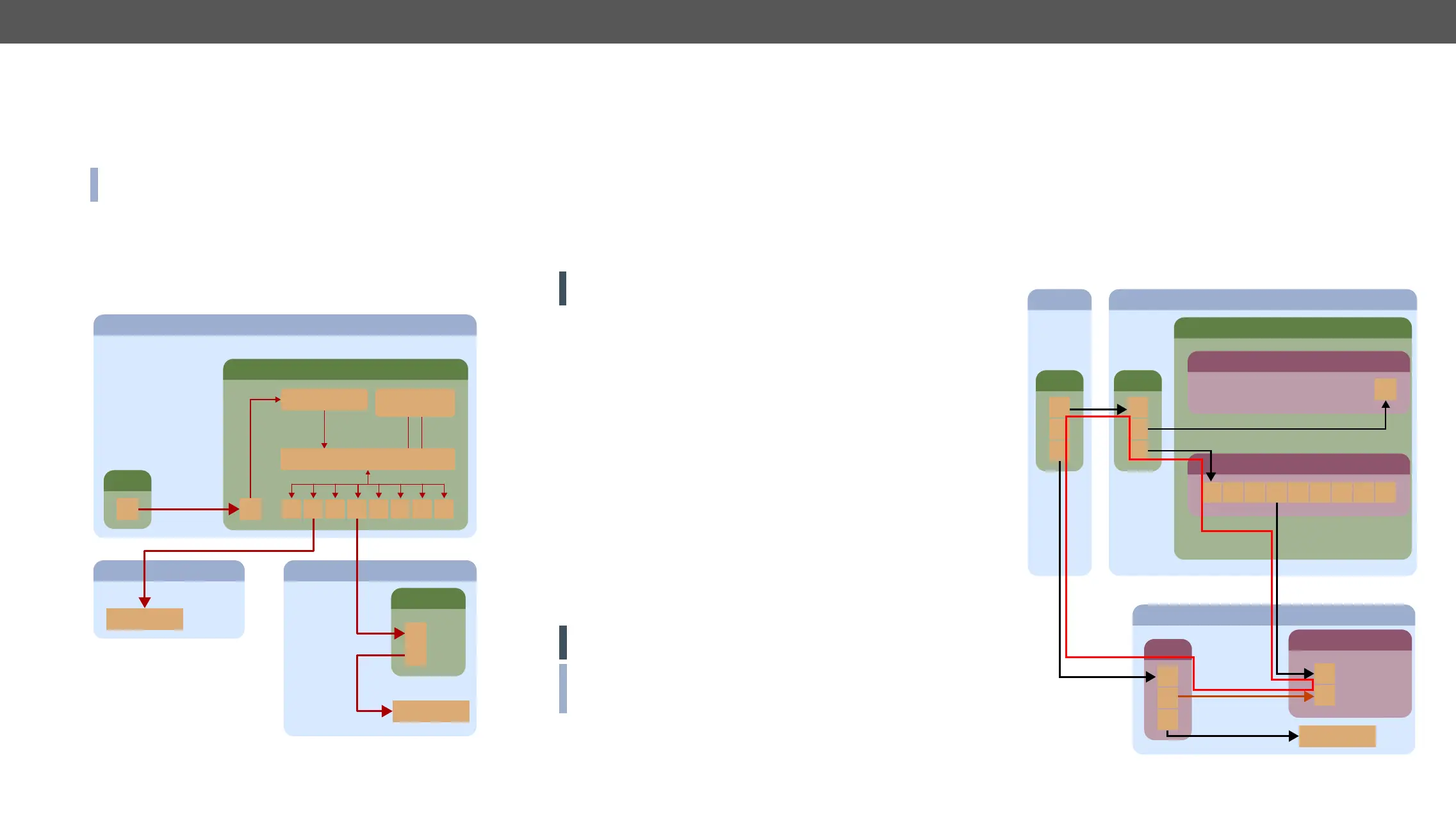
Ethernet and TPS Connectors for LAN
ROOM 1
MX-TPS I/O board
TPS converter
1
ETH 2 3 4 5 6 7 8
Ethernet switch
Video, audio,
RS-232, power
Downlinks
Switch
ETH
Uplink
ETH Uplink
ROOM 2
Ethernet device
ETH Downlink
ROOM 3
ETH Downlink
TPS extender
ETH
TPS
Ethernet device
TPS Downlink
If the TPS board is connected to LAN and the Ethernet channel is
enabled on a TPS port, the device which is connected* to this port is
supplied with a network connection. This connected device can be
a TPS extender or if the TPS port has the AUTO mode setting it also
can be a standard Ethernet equipment. The TPS port with AUTO mode
setting is able to recognize the type of the connection and if it is a
standard LAN the port swap into Ethernet fallback mode. In this case,
it is equivalent with a port of an Ethernet switch.
* If the remote power is disabled on a TPS port of a TPS card it works
as a HDBaseT compliant product and the connected device can be
a third-party HDBaseT compliant receiver (to the output board) or
transmitter (to the input board).
Always set the AUTO mode on a board before connecting a third-
party device!
Enable and Disable the Ethernet
The LAN can be enabled or disabled for every single TPS port with
protocol command. The example command is referred the 2nd port of
an MX-TPS output board.
The current state can be queried with the following command:
˃ {:TPS#2@SO=?}
The second parameter of the response represents the Ethernet state.
If it is 1 then the Ethernet is enabled for the 2nd port of the output
board. If it is 0 then the Ethernet is disabled for that port.
˂ (TPS#2@SO=A;1;0;0;1;00000000;00000000;0;0000;29;)
The same command is suitable for enabling or disabling this
parameter. To enable, use:
˃ {:TPS#2@SO=x;1}
˂ (TPS#2@SO=A;1;0;0;1;00000000;00000000;0;0000;34;)
To disable, swap the 1 to 0:
˃ {:TPS#2@SO=x;0}
˂ (TPS#2@SO=A;0;0;0;1;00000000;00000000;0;0000;34;)
ATTENTION! Connecting the MX-CPU card to the LAN via MX-TPS
board is not recommended.
INFO:
recommended to use in the setting command because the x does
not change the parameter so it remains unaltered.
For more information about the TPS command see the TPS and TPS2
Port section.
Avoid Causing an Ethernet Loop
A TPS board (actually the Ethernet switch of the board) can be uplinked
to the same LAN only once to avoid an Ethernet loop. In this case, if
the other network devices are not able to handle Ethernet loops the
LAN network may break down.
switch of the ROOM 2. The HDMI-TPS-TX95 in the ROOM 3 is connected
to the LAN via TPS link. If the installer does not know the transmitter
has already connected to the LAN via TPS and links the transmitter to
the switch – shown by the brown arrow in the picture – it results an
Ethernet loop – demonstrated by the red lines on below picture.
Ethernet Loop
MX-CPU2
ROOM 2
1 2 3 4 5 6 7 8
Switch
ETH
ETH
1
2
3
MX-TPS-IB-A
MX-FR frame
ROOM 1
Router
1
2
3
ROOM 3
Switch
ETH
1
3
HDMI-TPS-TX95
TPS
Ethernet device
2