MX-FR Series Modular Matrix Frames – User's Manual 95
Output Port Status
Description: Shows the actual status of the output ports. The response length changes regarding the frame
size. The meaning of the values changes regarding the output board types as they have different capabilities.
There are four DVI sinks connected to ports 2, 9, 11 and 12, nothing else.
Legend: <OUTPUT_D> may contain 9, 17, 33 or 80 hexadecimal numbers. Each number represents the state
for the corresponding output port. The meaning of the responded number depends on the actual board type
for that port. The binary representation of the responded hexadecimal numbers is shown below.
▪ Receiver Sense: TMDS termination present in the connected device.
▪ Hotplug Detect: Hotplug signal is presented by the connected device.
▪ Laser Enable: Optical transmitter is active on output.
▪ RX detect: Communication with the optical receiver is OK.
▪ HDMI mode: The incoming signal is HDMI.
▪ HDCP active: The incoming signal is encrypted.
INFO: Both Receiver Sense and Hotplug Detect can be used to check the attached sink device.
Format
Command {:OSD}
→
{:osd}
Response (OSD●<OUTPUT_D> )CrLf
←
(OSD 010000001011000000000000000000000)CrLf
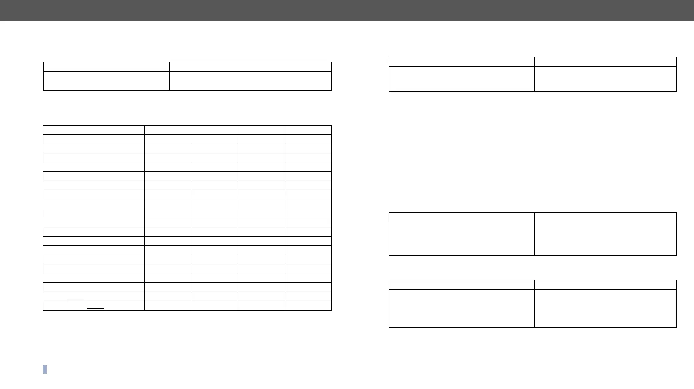
Board Type 2. bit 1. bit
MX-DVID-OB 0 0 0 receiver sense
MX-DVI-TP-OB 0 0 0 0
MX-DVI-TP-OB+ 0 0 0 hotplug detect
MX-DVI-OPT-OB, -R 0 0 0 0
MX-DVIDL-OB 0 0 0 hotplug detect
MX-DVIDL-OPT-OB 0 0 0 0
0 0 0 receiver sense
0 0 0 receiver sense
0 0 0
0 0 0 receiver sense
HDMI mode HDCP active RX detect laser enable
0 0 RX detect laser enable
MX-TPS-OB; -A; -S 0 0 0 TPS link pres.
0 0 0 receiver sense
MX-DVI-4K-OB 0 0 0 receiver sense
MX-AUDIO-OB 0 0 0 0
MX-TPS2-OB-P, -AP, -SP 0 0 0 TPS link pres.
MX-4TPS2-OB, -A, -S 0 0 0 TPS link pres.
MX-4TPS2--OB, -A, -S 0 0 0 receiver sense
All Port Status
Description: Shows the actual status of all input and output ports.
Legend: <INPUT_D> and <OUTPUT_D> is the same as for {:ISD} and {:OSD} commands.
I/O Port Commands
TPS and TPS2 Port
Port Parameters and Settings
Supported Boards:
▪ MX-TPS-IB, -A, -S; MX-TPS2-IB-P, -AP, -SP
▪ MX-4TPS2-4HDMI-IB, -A, S; MX-4TPS2-4HDMI-IB-P, -AP, -SP
▪ MX-4TPS2-4HDMI-OB, -A, S; MX-4TPS2-4HDMI-OB-P, -AP, -SP
▪ MX-TPS-OB, -A, -S; MX-TPS2-OB-P, -AP, -SP
Description:
case of the input and output ports.
The state of the 1st output is: HDBaseT mode is selected, Ethernet is enabled.
Setting the Parameters
The TPS mode of the selected port is set to Longreach, the Ethernet setting was not changed.
The response shows the new values. Use the 'x' character to keep the actual value of a parameter.
Format
Command {PS}
→
{ps}
Response (PS●<INPUT_D>,<OUTPUT_D>)CrLf
←
(PS 11333777001100000,010000001011000
00)CrLf
Format
Command
→
{:tps#1@so=?}
Response
<cmod>;<pwr>;<upl>;<qual>;<err>;<len>;
<rid>;<tmp>)CrLf
←
(TPS#1@SO=H;1;H;0;0;17161617;
23222020;0;0384;38;)CrLf
Format
Command
O>=<mod>;<eth>}
→
{:tps#1@so=L;x}
Response
<eth>;<cmod>;<pwr>;<upl>;<qual>;<err>;
<len>;<rid>;<tmp>)CrLf
←
(TPS#1@SO=L;1;H;0;0;17161617;23222020;0;
0384;38;)CrLf