MX-FR Series Modular Matrix Frames – User's Manual 94
Uploading the EDID Content
Description: EDID hex bytes can be written directly to the user programmable memory locations. The
sequence is the following:
Step 1.
Step 2. Router responds that it is ready to accept EDID bytes with (E_L_S)CrLf
Step 3. Send 1 block of EDID (1 block consist of 8 bytes of hex data represented in ASCII format) with
●<B1>●<B2>●<B3>●<B4> ●<B5>●<B6>●<B7>●<B8>}
Step 4. The router acknowledges with response (EL#<num>)
Step 5. Repeat steps 3 and 4 to send the remaining 31 blocks of EDID (32 altogether)
Step 6. After the last acknowledge, the router indicates that the EDID status changed by sending (E_S_C) CrLf
Legend: <num> represents the sequential number of every 8 byte part of EDID. <num> is between 1 and 32.
<B1>..<B256> are the bytes of EDID.
Full EDID uploaded to memory location U3.
Port Status Commands
Input Port Status
Description: Shows the actual status of the input ports. The response length changes regarding the frame
size. The meaning of the values changes regarding the input board types as the boards have different
functions and capabilities.
Format
Command
→
{wl#U3}
Response (E_L_S)CrLf
←
(E_L_S)CrLf
Command ●<B1>●<B2>●<B3>●<B4>●<B5>●
<B6>●<B7> ●<B8>}
→
Response (EL#<num>)CrLf
←
(EL#1)CrLf
Command ●<B9>●<B10>●<B11>●<B12>●
<B13> ●<B14>●<B15>●<B16>}
→
Response (EL#<num>)CrLf
←
(EL#2)CrLf
… …
Command ●<B249>●<B250>●<B251>●
<B252>●<B253> ●<B254>●<B255>●
<B256>}
→
Response (EL#<num>)CrLf
←
(EL#32)CrLf
Response (E_S_C)CrLf
←
(E_S_C)CrLf
Format
Command {:ISD}
→
{:isd}
Response (ISD●<INPUT_D> )CrLf
←
(ISD 113337770011000000000000
000000007)CrLf
Inputs 3-5 have DVI signals and inputs 6-8 have HDMI signals. The second input board is a DVI board. Input
11 and 12 have DVI signals. The Test Input port has an HDMI signal.
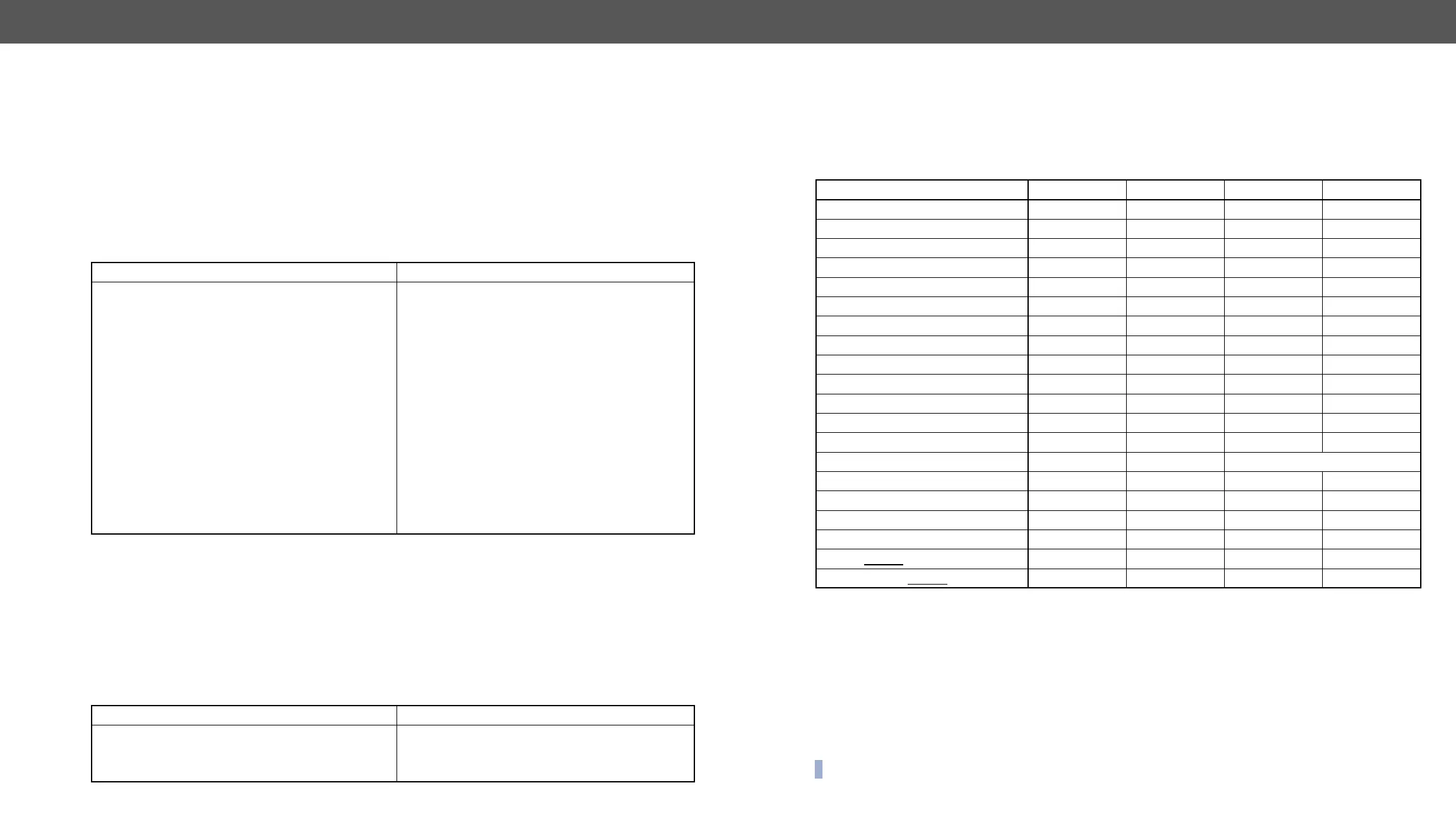
Legend: <INPUT_D> may contain 9, 17, 33 or 80 hexadecimal numbers. Each number represents the state
for the corresponding input port. The meaning of the responded number depends on the actual board (port)
type. The binary representation of the responded hexadecimal numbers is shown below.
▪ Source 5V: The connected source sends 5V.
▪ Clock detect: TMDS clock is present.
▪ Laser + Clock: Laser detected and TMDS clock is present.
▪ Signal Detect: Video signal is present (TMDS stream can be recognized).
▪ HDMI mode: The incoming signal is HDMI.
▪ HDCP active: The incoming signal is encrypted.
▪ TX detect: Communication with optical transmitter is OK.
▪ Analog signal: Video signal is present on the analog input.
▪ Digital signal: Video signal is present on the digital input.
INFO: Both Clock Detect and Signal Detect can be used to check if there is an incoming signal.
Board Type 2. bit 1. bit
MX-DVID-IB 0 0 0 clock detect
MX-DVI-TP-IB 0 0 0 clock detect
MX-DVI-TP-IB+ 0 0 0 clock detect
MX-DVI-OPT-IB 0 0 0 laser + clock
MX-DVIDL-IB 0 0 0 clock detect
MX-DVIDL-OPT-IB 0 0 0 laser + clock
0 HDMI mode signal detect source 5V
0 HDMI mode signal detect source 5V
0 HDMI mode signal detect source 5V
0 HDMI mode signal detect source 5V
HDCP active HDMI mode TX detect clock detect
analog signal HDCP active digital signal source 5V
MXD-UMX-IB analog signal HDCP active digital signal source 5V
MX-3GSDI-IB video detect audio detect type: 01=SD, 10=HD, 11=3G
HDCP active HDMI mode clock detect source 5V
MX-4K-DVI-IB HDCP active HDMI mode clock detect source 5V
MX-TPS-IB, -S, -A HDCP active HDMI mode clock detect TPS link pres.
MX-TPS2-IB-P, -AP, -SP HDCP active HDMI mode clock detect TPS link pres.
MX-4TPS2-IB, -A, -S HDCP active HDMI mode clock detect TPS link pres.
MX-4TPS2--IB, -A, -S HDCP active HDMI mode clock detect source 5V