MX-FR Series Modular Matrix Frames – User's Manual 84
Displaying the Current Connection States of the Outputs
Description:
frame size. The response below supposes a router having 17 outputs.
INFO: The MX-CPU2 responds the connection of Preview Output port as well. The earlier 16x16 or 32x32
frames responded 16 and 32 outputs but with MX-CPU2 the response will be 17 and 33 correspondingly.
Legend 1
means that output 5 is connected to input 4. All <Ox> indexes are two digit ASCII characters (01, 02, 04, etc.).
: Viewing connection for all outputs. Input 2 is connected to outputs 1, 2 and 3. Input 5 is
connected to outputs 4, 5 and 6. Input 8 is connected to outputs 7 through 17.
INFO: If an output is locked, muted, or both locked and muted, the response format changes. If outputs
are muted you get a letter 'M', if locked a letter 'L' and if muted and locked at the same time 'U' before the
2 digit numbers.
Legend 2: Any <Ox> indexes can be a two digit number, or there can be a leading character showing the mute
Viewing connection for all outputs. Input 2 is connected to outputs 1, 2 and 3. Output 1 is
muted. Output 2 is locked. Output 3 is muted and locked. Input 5 is connected to outputs 4, 5 and 6. Input 8
is connected to outputs 7 through 16.
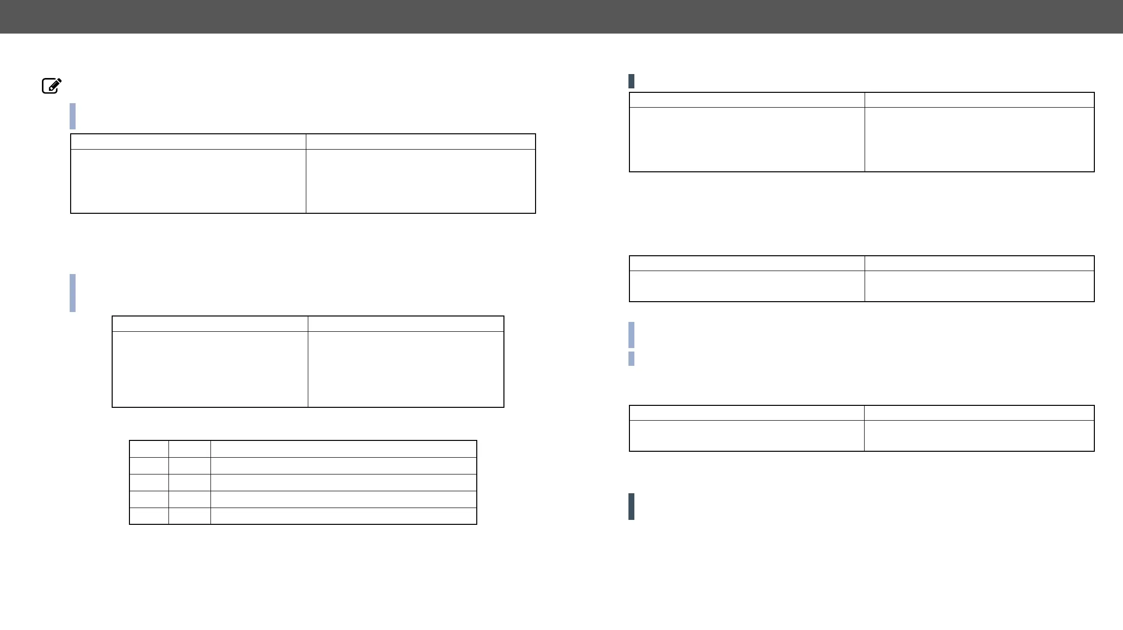
Format
Command {VC}
→
{vc}
Response (ALL●<O1>●<O2>●<O3>●<O4>●<O5>●
<O6>●<O7> ●<O8>●<O9>●<O10>●
<O11>●<O121>●<O13>●<O14>●<O15>●
<O16> ●<O17>)CrLf
←
(ALL 02 02 02 05 05 05 08 08 08 08 08 08 08
08 08 08 08)CrLf
Format
Command {VC}
→
{vc}
Response (ALL●<O1>●<O2>●<O3>●
<O4>●<O5>●<O6>●<O7>●
<O8>●<O9>●<O10> ●<O11>●
<O12>●<O13> ●<O14>●
<O15>●<O16> ●<O17>)CrLf
←
(ALL M02 L02 U02 05 05 05 08 08 08
08 08 08 08 08 08 08 08)CrLf
Legend
<Ox> <in²> <Ox> is connected to <in²>, <Ox> neither muted nor locked.
<Ox> M<in²> <Ox> is connected to <in²>, <Ox> is muted, and unlocked.
<Ox> L<in²> <Ox> is connected to <in²>, <Ox> is not muted, but locked.
<Ox> U<in²> <Ox> is connected to <in²>, <Ox> is muted and locked.
Listing the Mute/Unmute States of All Outputs
ATTENTION! The response length depends on the frame size.
Legend: All <Mx> indexes are one digit numbers, showing the mute state for the corresponding output. If
<Mx> equals 0 the output x is unmuted. If <Mx> equals 1, the output x is muted.
Output 1, 3 and 4 are muted, the other outputs are not muted.
Description: Mute output <out>. The output signal is turned off.
Output 3 is muted. No signal is present on output 3 now.
INFO:
connection can be easily restored with an unmute command.
INFO: Switching a muted output does not unmute the output.
Description: Unmute output <out>.
Output 3 is unmuted. Now output 3 is switched to the input it was connected to prior to the
mute command.
ATTENTION!
been changed with the muting command, only the output was disabled.
Format
Command {VM}
→
{vm}
Response (MUT●<M1>●<M2>●<M3>●<M4>●
<M5>●<M6>●<M7>●<M8>●<M9>●
<M10>●<M11>●<M12>●<M13>●
<M14>●<M15>●<M16>●<M17>)CrLf
←
(MUT 1 0 1 1 0 0 0 0 0 0 0 0 0 0 0 0 0)CrLf
Format
Command {#<out>}
→
{#03}
Response (1MT<out²>)CrLf
←
(1MT03)CrLf
Format
Command {+<out>}
→
{+03}
Response (0MT<out²>)CrLf
←
(0MT03)CrLf