3. Product Overview MX-FR Series Modular Matrix Frames – User's Manual 12
3
Product Overview
The following sections are about the physical structure of the device, input/
output ports and connectors:
ç
ç
ç
ç
ç
ç
ç
ç MX-FR33R
ç MX-FR33L
ç MX-FR17
ç MX-FR9
ç
ç
ç
signal transmission. The hybrid architecture allows signal routing
between boards even if they have different connectors. This way any
input can be routed to any or more outputs if the output interface is
capable of transmitting the signal. For example, a DVI source can
be routed to an HDMI sink, but HDCP-encrypted sources cannot be
routed to non-HDCP capable DVI sinks.
Available interface types include DVI-D single- and dual-link, HDMI,
Router Frames
needs various input and output interface boards are available, that can
be mixed in the same frame without limitation.
INFO: The maximum number of input and output ports includes
the Test input and Preview output port of the MX-CPU2 processor
board.
The mute-, lock-, and crosspoint states are stored in the matrix, all
E.g. if an MX-TPS-IB had been installed previously in a matrix and an
MX-TPS-IB-A board was installed later, the previous settings would be
applied to the board.
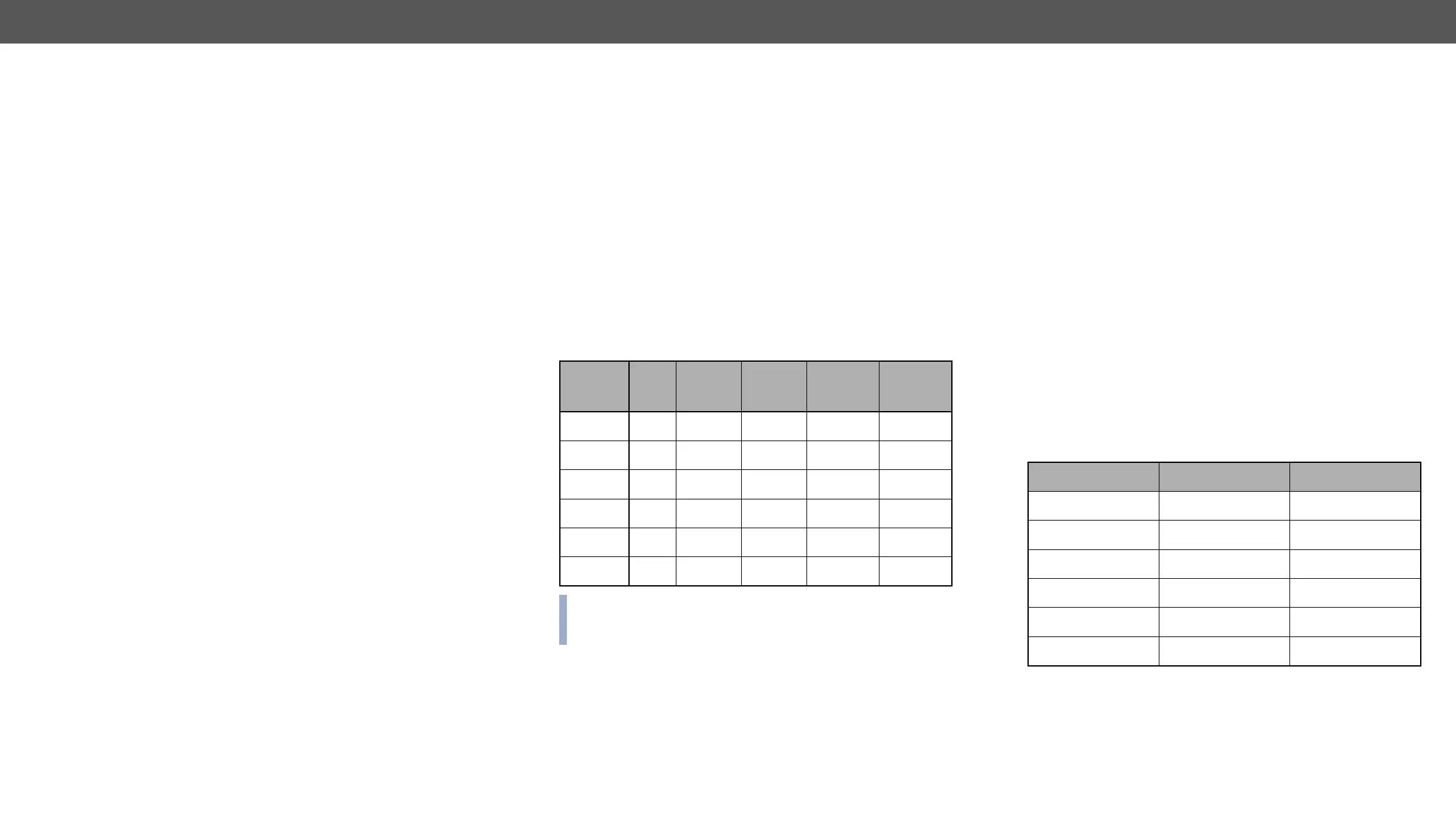
Frame
type
Rack
height
input
boards
input
ports
output
boards
output
ports
MX-FR9 4U 1 9 1 9
MX-FR17 4U 2 17 2 17
MX-FR33L 6U 4 33 4 33
MX-FR33R 7U 4 33 4 33
MX-FR65R 15U 8 65 8 65
MX-FR80R 15U 10 80 10 80
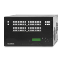
MX-CPU2 Processor Board
The CPU board is necessary for the router frame to work. This board is
responsible for controlling the matrix and storing the settings.
Test Input and Preview Output Ports
The MX-CPU2 board has a TEST INPUT and a PREVIEW OUTPUT port.
Although these ports have special functions they can be used as
MX-FR80R and MX-FR65R
Used in the MX-FR80R (and MX-FR65R) router frame, the Preview
output is directly connected to the 80th output port with a DVI splitter.
Therefore this port always outputs the same signal as the 80th output,
even if it uses a different interface (TP, OPT, etc.).
The 80th input port of the crosspoint is multiplexed between the
Test input port and the 8th port of the 10th input board. This switch
is independent from the crosspoint state. The selected port (Test
input or Input board #10) will be available as the 80th input on the
crosspoint switch.
Other Frames
All other frames use the Test input and Preview output just like any
other ports. These ports are referred as the last port in the crosspoint.
Other Connectors
The MX-CPU2 board has Ethernet, serial, and alarm ports as well.
Frame Type Test Input Preview Output
MX-FR9 in 9 out 9
MX-FR17 in 17 out 17
MX-FR33L in 33 out 33
MX-FR33R in 33 out 33
MX-FR65R in 80 out 80
MX-FR80R multiplexed in 80 distributed out 80