3. Product Overview MX-FR Series Modular Matrix Frames – User's Manual 13
MX-FR65R Limitations
The MX-FR65R matrix frame is physically identical to the MX-FR80R.
MX-FR65R allows only 8.
The frame has 10 physical board slots but will not boot up when more
than 8 input or output boards are inserted. Only the number of boards
is limited thus they can be used in any of the physical slots. However
to gain access to the Test input and Preview output ports on the MX-
CPU2 it is recommended to leave the last slot empty.
For example, if the input slot #1 is empty, there can be 8 input boards
in slots #2 to #9 and the slot #10 left empty. In this case the 65 input
ports can be accessed with port numbers 9-72 and 80.
MX-CPU2 Board Features
modular matrix routers:
All older models can be upgraded with MX-CPU2 processor board.
Changes with MX-CPU2 upgrade
▪ Extra I/O ports – Get an additional DVI-HDCP input and output
port.
▪ Ethernet control
connections.
▪ Combine HDCP and non-HDCP boards – Any interface board
combination is possible in the same frame.
Older models New models
MX16x16DVI-Pro
MX32x32DVI-Pro
MX32x32HDMI-Pro
MX16x16HDMI-Pro
MX32x32DVI-HDCP-Pro
MX16x16DVI-HDCP-Pro
MX-DVI-FR16
MX-DVI-FR32
MX-DVI-FR32R
MX-FR9
MX-FR17
MX-FR33(L)
MX-FR33R
MX-FR65R
MX-FR80R
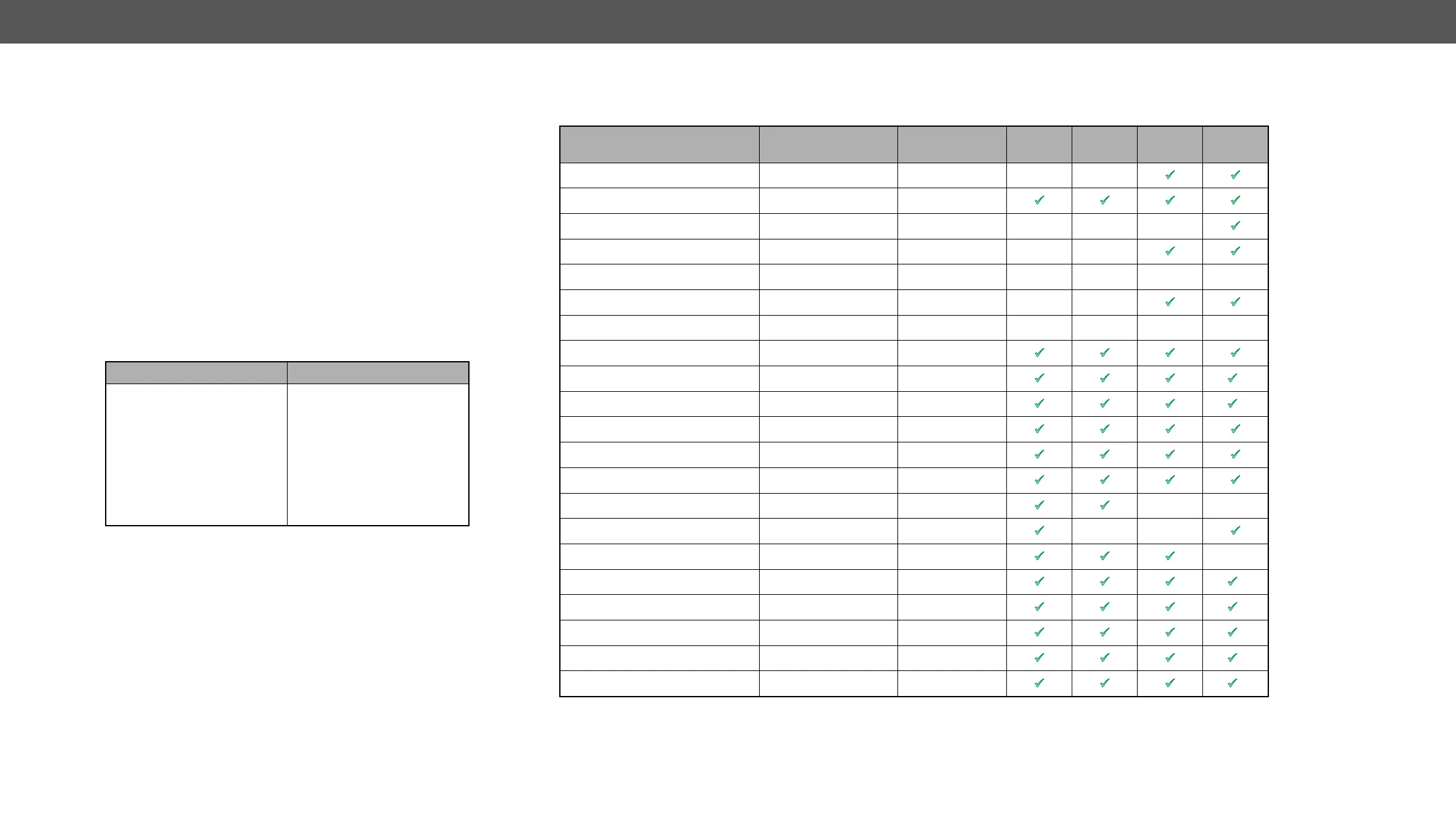
Input Boards
Several input interface boards are available. Each model has different capabilities and functions. Below table shows a summary of the main features.
1
Any DVI connector can be plugged in but only digital pins are connected.
2
3
TM
on the TPS ports.
4
Model
Default
Connectors
Optional
Connectors
Capability
Capability
EDID
Emulation
Cable
MX-DVID-IB 8x DVI-I (D)
1
- - -
ü ü
MX-DVI-4K-IB 8x DVI-I (D)
1
-
ü ü ü ü
MX-DVI-TP-IB - - - -
ü
MX-DVI-TP-IB+ - - -
ü ü
MX-DVI-OPT-IB-… 8x optical - - - - -
MX-DVIDL-IB 4x DVI-I (D) (dual link) - - -
ü ü
MX-DVIDL-OPT-IB-… 4x optical (dual link) - - - - -
MX-DVI-HDCP-IB 8x DVI-I (D)
1
-
ü ü ü ü
MX-DVII-HDCP-IB 8x DVI-I -
ü ü ü ü
2
MXD-UMX-IB 8x DVI-I
ü ü ü ü
2
MX-HDMI-IB 8x HDMI -
ü ü ü ü
MX-HDMI-TP-IB -
ü ü ü ü
MXD-HDMI-TP-IB
ü ü ü ü
MX-HDMI-OPT-IB-… 8x optical -
ü ü
- -
MX-3GSDI-IB -
ü
- -
ü
MX-CPU2 Test Input 1x DVI-I (D)
1
-
ü ü ü
-
MX-TPS-IB, -A, -S 8x TPS
ü ü ü ü
3
MX-HDMI-3D-IB, -A, -S 8x HDMI
ü ü ü ü
3
MX-TPS2-IB-P, -AP, -SP 8x TPS
ü ü ü ü
3
MX-4TPS2-4HDMI-IB, -A,- S 4x TPS, 4x HDMI
ü ü ü ü
3
MX-4TPS2-4HDMI-IB-P, -AP, -SP 4x TPS
4
, 4x HDMI
ü ü ü ü
3