2. Installation MX-FR Series Modular Matrix Frames – User's Manual 10
WARNING! The I/O boards and the CPU board are not hot-
inserting a board.
Important Notices about the Boards
have different connectors on the motherboard in the matrix, thus, they
have dedicated slots as indicated in the rear plate. In general:
▪ CPU board is placed in the top position always.
▪ Output boards are located below the CPU board.
▪ Input boards are located in the bottom slots.
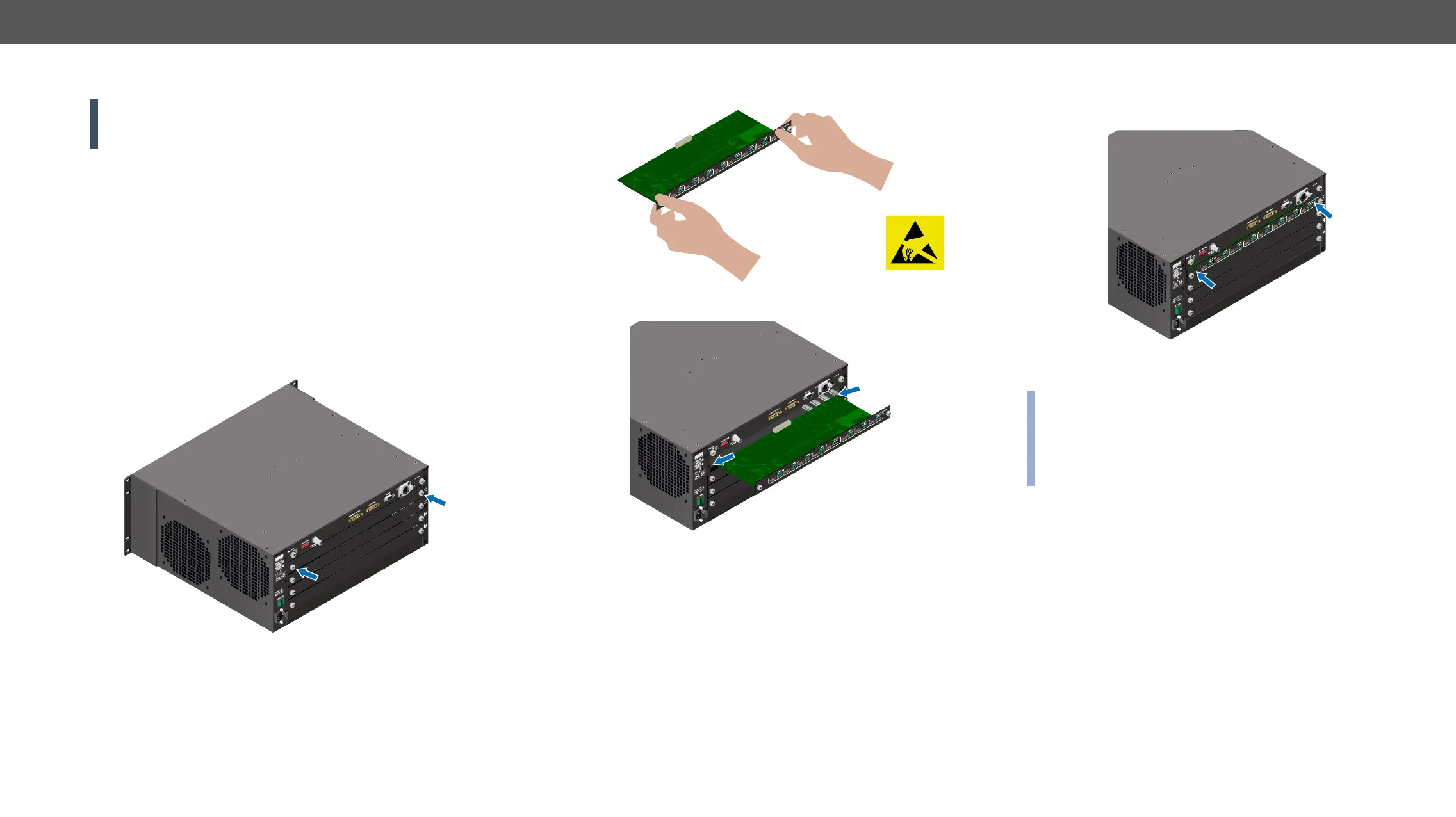
Installing a Board
Step 1. Make sure the matrix is powered off.
Step 2.
previously installed board.
CPU
Step 3. Take the board by touching the metal plate only, to prevent
ESD-caused problems.
Step 4. Insert the edge of the board in the slot at both sides.
8CH OUTPUT BOARD FOR HDMI WITH 3D AND ANALOG AUDIO
MX-HDMI-3D-OB-A
OUT 1
OUT 2
OUT 3
OUT 4
OUT 5
OUT 6
OUT 7
OUT 8
CPU
8CH OUTPUT BOARD FOR HDMI WITH 3D AND ANALOG AUDIO
MX-HDMI-3D-OB-A
OUT 1
OUT 2
OUT 3
OUT 4
OUT 5
OUT 6
OUT 7
OUT 8
Step 5. Gently push the board in until it stops, then press the plate at
the indicated places at once. Thus, the connector of the board
and the motherboard will be put together.
Step 6.
with PZ1 head.
INFO: The mute-, lock-, and crosspoint states are stored in the
in a matrix and an MX-TPS-IB-A board was installed later, the
previous settings would be applied to the board.
CPU
8CH OUTPUT BOARD FOR HDMI WITH 3D AND ANALOG AUDIO
MX-HDMI-3D-OB-A
OUT 1
OUT 2
OUT 3
OUT 4
OUT 5
OUT 6
OUT 7
OUT 8