34 CHAPTER 4: OPERATION
MOVE S2
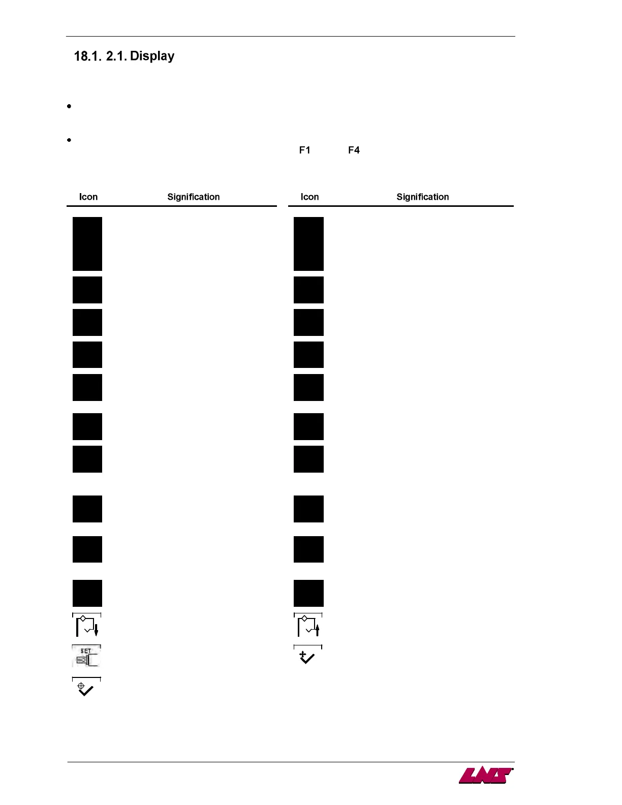
The liquid crystal display provides the operator with all the necessary data, both for handling the bar
feeder and for maintenance.
The upper portion of the display has eleven lines and is reserved for the reading of text.
Error messages are usually displayed with their diagnostics.
The lower portion of the display is reserved for the display of icons. The icons indicate to the
operator which functions are attributed to keys
through .
The icons available are the following:
Referencing position
Set up
Escape
Stop after machining one bar stock
Pusher forward (picture may be
reversed)
Load a bar stock in the guiding elements
Pusher reverse (picture may be
reversed)
Confirm the unloading of a bar stock out of
the guiding elements
Validate Cancel
Cut positioning in manual
mode (picture may be reversed)
Teach data
Extract the bar out of the clamping
device of the lathe (picture may be
reversed)
Confirm. In setup mode, the button
must be hold for 3 seconds to
validate the change.
Increment data in offset correction mode
Decrement data in offset correction mode
Closing bearing support pusher Opening bearing support pusher
Change guiding elements Validation for the changes of guiding
elements
Validation for the return position of
the fingers once the guiding
elements positioned