CHAPTER 2 INSTALLATION
8
The front panel is shown in Figure 2-1. Pin definition and pin connection of the console port are listed in
the following tables.
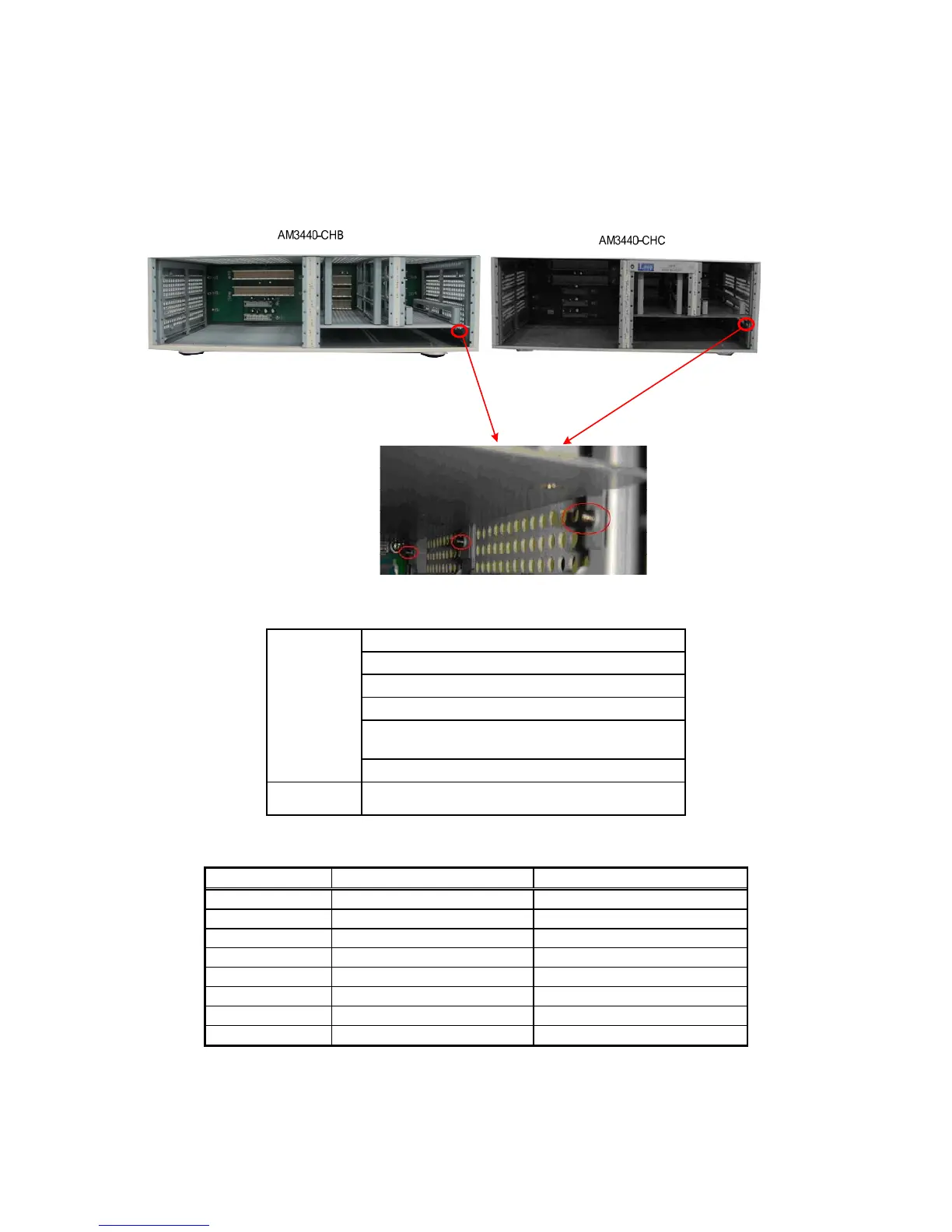
NOTE: If you see protruding screw heads on the slot 3 of CHB or slot 5 of CHC as shown in the figure
below, do not plug the TDMoE card into these two locations because the card might be
damaged.
Table 2-1 Ethernet Function Table
Four 10/100/1000 Mbps, auto-negotiation
Auto MDI/MDIX
Auto-crossover function support
Flow control
Force mode: duplex (half/full),
speed(10/100/1000M)
Ethernet
Functions
Egress Rate Limiting
Connector RJ45
Table 2-2 RJ45 for Ethernet Port
Pin Number Signal Signal Direction
1 Transmit Data + Output from TDMoE card
2 Transmit Data - Output from TDMoE card
3 Receive Data + Input to TDMoE card
4 No Connection
5 No Connection
6 Receive Data - Input to TDMoE card
7 No Connection
8 No Connection