CHAPTER 9 Appendix B: 1 + 1 Protection between TDMoE and QE1/T1 Card
57
9. Appendix B: 1 + 1 Protection between TDMoE and QE1/T1 Card
9.1. Overview
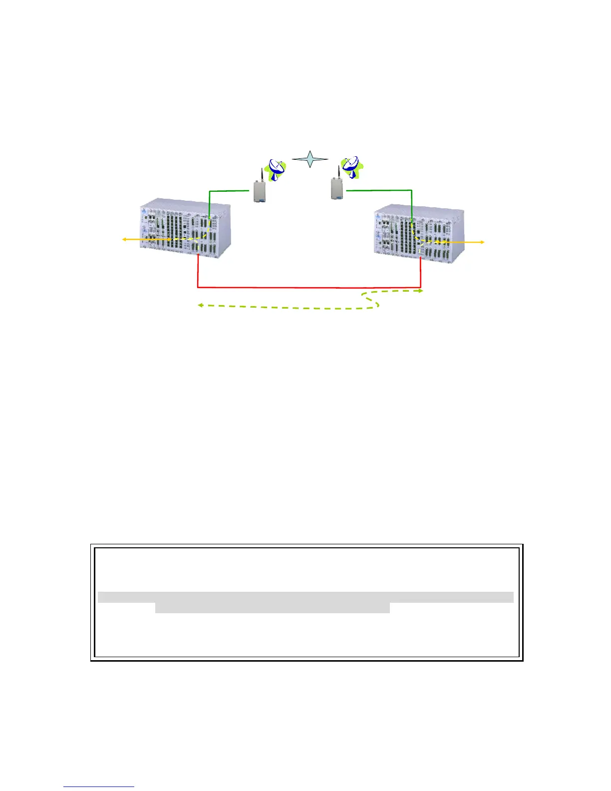
TDMoE card supports 1 + 1 protection function with QE1/T1 card, which is illustrated in the figure below.
This chapter predominantly provides users with step by step guide for configuring 1 + 1 protection.
AM3440#2
AM3440#1
QE1/T1
(slot2 port1)
TDMoE and QE1/T1
1+1 protection
Ethernet Radio
Ethernet Radio
TDMoE
(slot1 port1)
Master
Slave
Backup line
Leased line
Master
Slave
TDMoE
(slot1 port1)
QE1/T1
(slot2 port1)
T1 (slot10
port1)
T1 (slot10
port1)
Figure 9-1 TDMoE and QE1/T1 1 + 1 Protection
To successfully setup 1 + 1 protection, follow the steps below in sequence:
1. Configuring TDMoE card:
y Configure the interface mode
y Configure the interface framing mode
y Configure bundle IP
y Assign timeslots to an interface
y Configure parameters for each bundle
2. Configuring AM3440 Controller:
y Configure QDS1 1:1 protection
y Configure TSI map
y Activate the TSI map
y Configure Clock Source
For both AM3440#1 and AM3440#2, the configuration procedure is identical. In this section, the setup
instructions of the AM3440#1 are applied as an example.
NOTE:
When using 1+1 Protection with Quad E1/T1 card, two plug-in cards must be inserted next to each
other as a pair so that one plug-in card can be used to protect the other.
For example: A pair of TDMoE and Quad E1/T1 cards should be installed in one of the following slot
groupings: [1&2], [3&4], [5&6], [7&8], [9&10] or [11&12].
Each TDMoE and Quad E1/T1 card has four ports. The ports of one card protect the corresponding
ports of the other card. For example, Port 1 of the protection card protects Port 1 of the other card.
Similarly, Port 2 of the protection card protects Port 2 of the other card, etc.