CHAPTER 3 OPERATION
9
3. OPERATION
3.1. Alarm
When the TDMoE card reports an alarm condition, such as loss of synchronization, the ALARM will
cause the LED on the front panel to light. Each alarm can be individually enabled or disabled. The
alarm types are listed in the table as below.
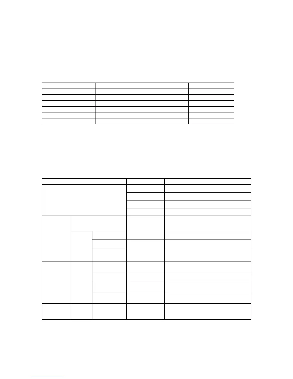
Table 3-1 Alarm Default – for System and Line
Alarm Option Default
ARP/bundle DISABLE,MAJOR,CRITICAL,MINOR DISABLE
Rx-Lost/bundle DISABLE,MAJOR,CRITICAL,MINOR DISABLE
Cell-Lost/bundle DISABLE,MAJOR,CRITICAL,MINOR DISABLE
Underrun/bundle DISABLE,MAJOR,CRITICAL,MINOR DISABLE
Overrun/bundle DISABLE,MAJOR,CRITICAL,MINOR DISABLE
Ethernet Link Down DISABLE,MAJOR,CRITICAL,MINOR DISABLE
3.2. LED
The front panel of the TDMoE has multi-color LEDs for operation and error indications. The indication is
either off, steady on, or flickering. The following table lists each LED and its color and the meaning it
represents. Note that when powering up and self test is in progress, the unit front panel LEDs are also
used to indicate fault conditions.
Table 3-2 LED Indication for Main Unit
LED Color Indication
Off No power, card failure or LED failure
Green Active
Flashing Green Hard waving
ACT
Red Alarm
ACT Flashing Green Data is being transmitted or received
through Ethernet port
1000M Amber Link with 1000M bps
100M Green Link with 100M bps
10M
Eth3 and
Eth4
SPEED
ACT
Off Link with 10M bps
10 Off Link with 10M bps
1000 Amber Link with 1000M bps
100 Green Link with 100M bps
Eth1 and
Eth2
(Electrical)
SPEED
ACT Flashing Green Data is being transmitted or received
through Ethernet port
Eth1 and
Eth2
(Optical)
SPEED 1000
100
Amber
Green
WAN port is link up