215585 172 Revision A
$ %
&
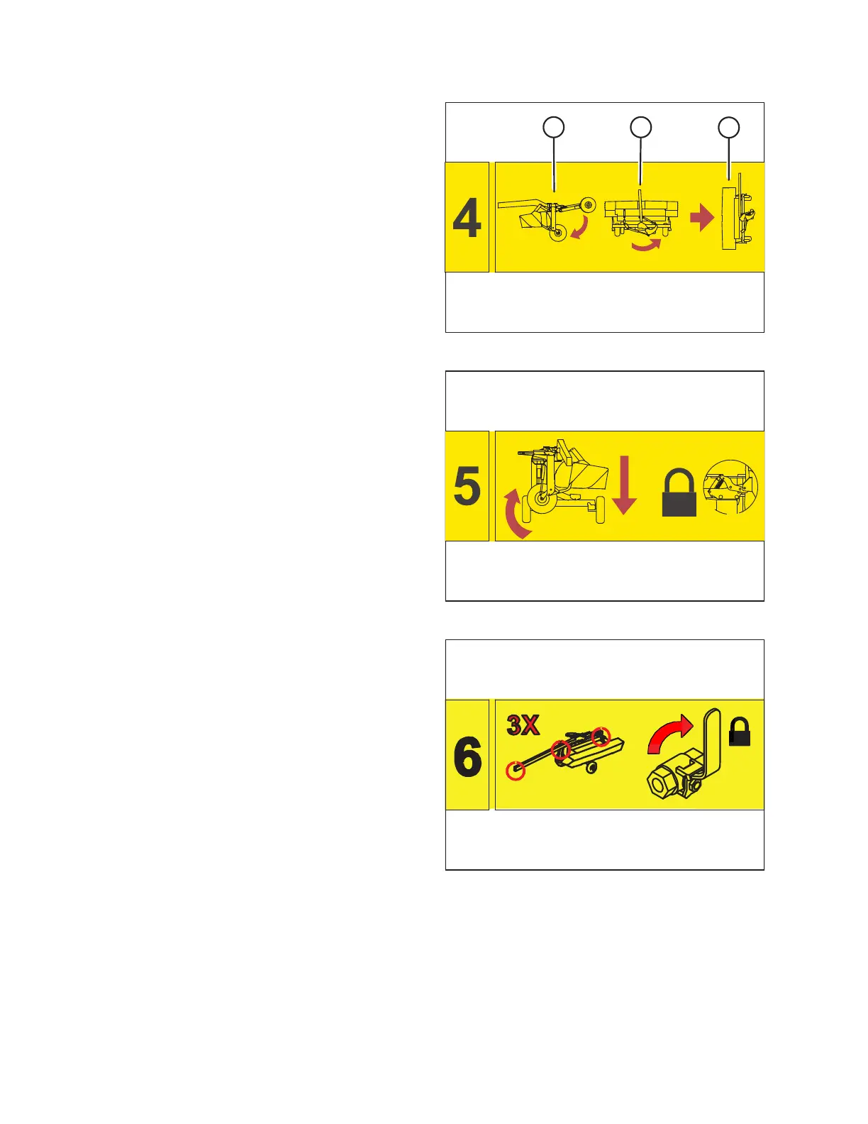
Figure 9.18: Transport Assembly Rotation
7. Operate the hitch swing control lever to lower transport
wheels (A) and hold the lever until the rotary disc pull-type
is lifted off the ground.
8. Continue to hold the hitch swing control lever so that
rotary disc pull-type (B) rotates to the left and under
the hitch.
9. Release the hitch swing control lever when rotary disc pull-
type (C) stops rotating.
Figure 9.19: Transport Assembly Lowering
10. Operate the lift control lever to lower the rotary disc pull-
type onto the transport assembly, raise the field wheels,
and engage the transport latch onto the hitch.
IMPORTANT:
Once the latch has engaged, do NOT operate any hydraulic
circuits.
Figure 9.20: Hydraulic Lockout
11. Close the steering lock-out valve and the two lift cylinder
lock-out valves by turning the handles to the closed
position. For instructions, refer to Figure 9.21, page 173
and Figure 9.22, page 173.
TRANSPORTING THE ROTARY DISC PULL-TYPE