214880 150 Revision A
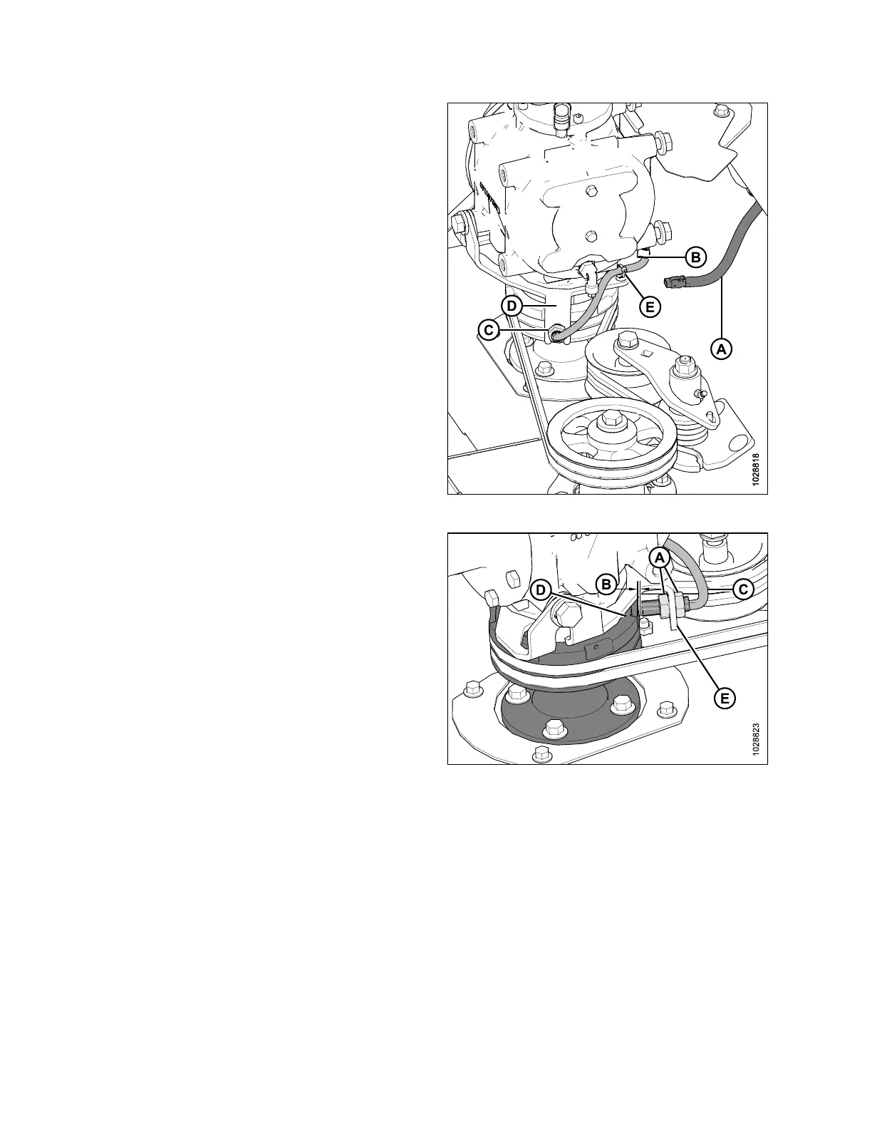
Figure 4.185: Header Disc Speed Sensor
4. Disconnect wire harness (A) from speed sensor
connector (B).
5. Remove fir tree clip and cable tie (E). Retain clip for
reinstallation.
6. Remove nut (C) from end of sensor and remove sensor
from bracket (D).
7. Remove nut from the end of new sensor, install the new
sensor into bracket (D) and secure with nut (C).
8. Connect the sensor wire (B) to harness (A).
NOTE:
Ensure wires are clear of belt and pulley.
9. Secure with fir tree clip (E) and new cable tie.
Figure 4.186: Header rpm Sensor
10. Adjust nuts (A) as required to achieve a 2– 3mm
(1/16–1/8 in.) gap (B) between the sensor (C) and the
pulley (D). Ensure sensor face and pulley face are parallel.
Bend bracket (E) as required.
11. Tighten nuts (A) to 12 Nm (9 lbf·ft).
12. Reinstall the driveshield. For instructions, refer to 4.10.2
Installing Driveshields, page 147.
13. Start windrower, engage header, and check operation of
speed sensor on monitor. The sensor may require re-
calibrating. Refer to the windrower operator’s manual.
MAINTENANCE AND SERVICING